 |
|||
|
|
|||
|
|
|||
| ||||||||||
|
|
 69
TM 9-2320-312-24-2
Truck Engine
Disassembly and Assembly Section
NOTICE
Care must be taken to ensure that fluids are contained
during performance of inspection, maintenance, test-
ing, adjusting and repair of the product. Be prepared to
collect the fluid with suitable containers before open-
ing any compartment or disassembling any compo-
nent containing fluids.
Refer to Special Publication, NENG2500, "Caterpillar
Tools and Shop Products Guide" for tools and supplies
suitable to collect and contain fluids on Caterpillar
products.
Dispose of all fluids according to local regulations and
g00611536
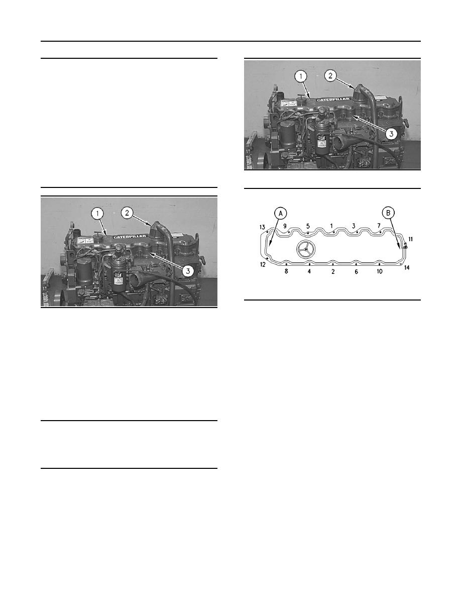
Illustration 173
mandates.
g00786705
Illustration 174
g00611536
Illustration 172
Bolt tightening sequence for the valve mechanism cover
(A) Rear
1. Remove breather assembly (2) from valve
(B) Front
mechanism cover (1).
1. Position valve mechanism cover (1) and the seal
2. Remove the bolts that hold valve mechanism
on valve mechanism cover base (3). Cut the seal
cover (1) to valve mechanism cover base (3).
to length. Apply 4C-9612 Silicone Sealant on
both sides of the seal joint.
3. Remove the seal from the valve mechanism
cover.
2. Install the bolts. Tighten the bolts in a
numerical sequence to a torque of 12 3 Nm
Installation Procedure
(106 27 lb in).
Note: Inspect the O-ring seal of the breather
NOTICE
assembly. Replace the O-ring seal, if necessary.
Keep all parts clean from contaminants.
3. Position breather assembly (2) on valve
Contaminants may cause rapid wear and shortened
mechanism cover (1). Tighten the bolt for
component life.
breather assembly (2) to a torque of 7 2 Nm
(62 18 lb in).
|
|
Privacy Statement - Press Release - Copyright Information. - Contact Us |