 |
|||
|
|
|||
|
Page Title:
Illustration 149 Schematic Drawing |
|
||
| ||||||||||
|
|
 61
TM 9-2320-312-24-2
Truck Engine
Disassembly and Assembly Section
10. Install idler gear (15) on idler shaft (17). Install
the shaft and gear assembly in the flywheel
housing. Start with the bolt that is marked T.
Tighten bolts (18) and (19) in a clockwise
position to a torque of 100 Nm (74 lb ft). Again
tighten bolts to a torque of 175 Nm (130 lb ft).
g00759811
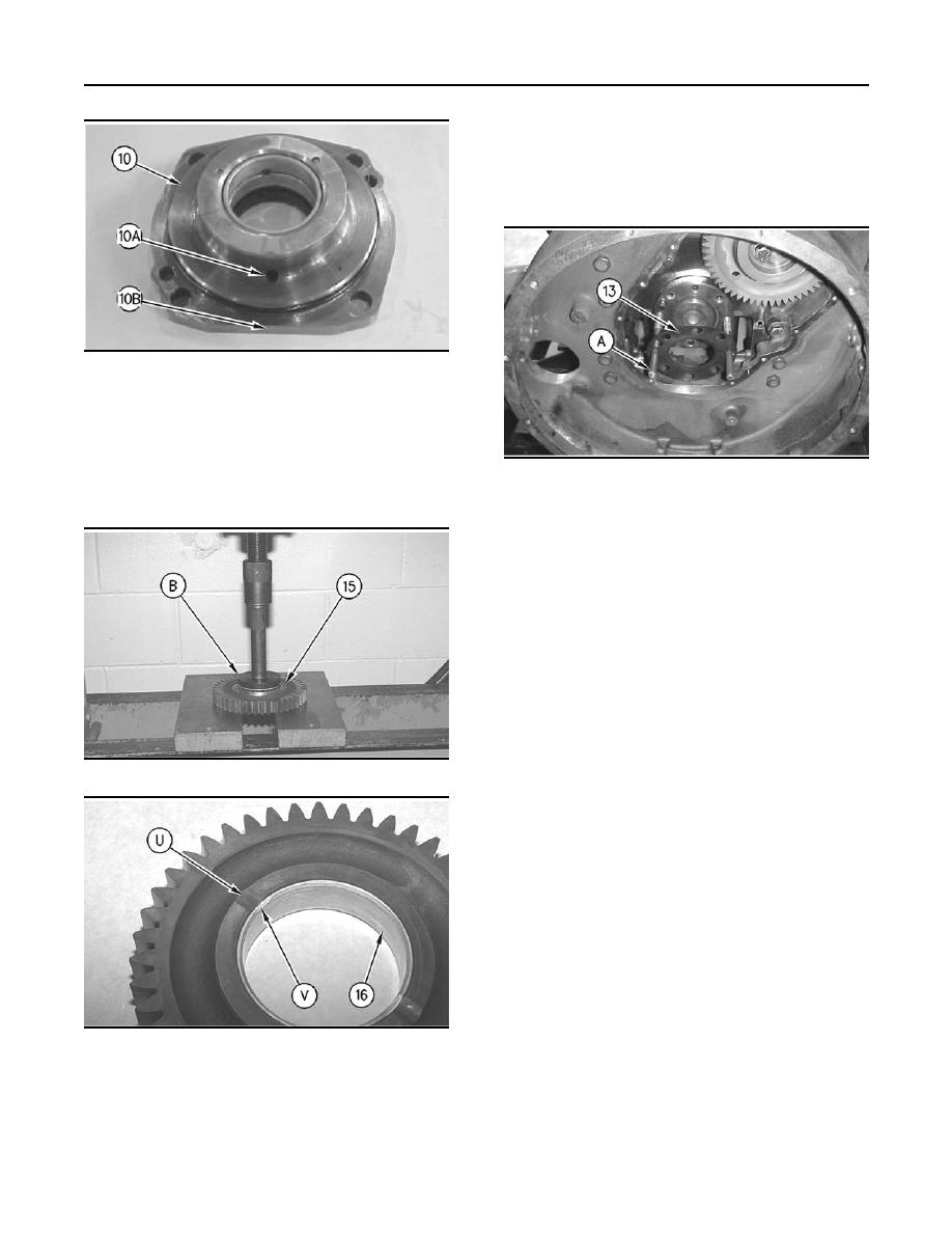
Illustration 149
Note: Ensure that flat side (10B) of cover (10) is
against the flywheel housing. This will ensure that
oil passage (10A) is located toward the flywheel
housing.
g00759821
Illustration 152
8. Install PTO shaft (5) and adapter assembly (10)
into RPTO housing (26) and install bolts (12).
11. Install Tooling (A) in the crankshaft. Install gasket
(13) and crankshaft gear (14).
12. Install the gasket (20), cover (21), bolts (25),
and the washers.
13. Install O-ring seal (22), crankshaft rear seal (23),
and bolts (24).
End By:
a. Install the flywheel. Refer to Disassembly and
Assembly, "Flywheel - Install".
g00760157
Illustration 150
g00760159
Illustration 151
9. Install bearing (16) in gear (15) with Tooling (B).
Note: Bearing Relief Groove (U) must line up
with the Relief Groove (V) in gear (15) within two
degrees. Bearing (16) must not extend beyond
either face of gear.
|
|
Privacy Statement - Press Release - Copyright Information. - Contact Us |
