 |
|||
|
|
|||
|
Page Title:
Test Step 7. Test ECM Vehicle Speed Inputs by Using the Speedometer Special Test |
|
||
| ||||||||||
|
|
 416
TM 9-2320-312-24-2
Troubleshooting Section
Test Step 7. Test ECM Vehicle Speed
Inputs by Using the Speedometer Special
Test.
g00643436
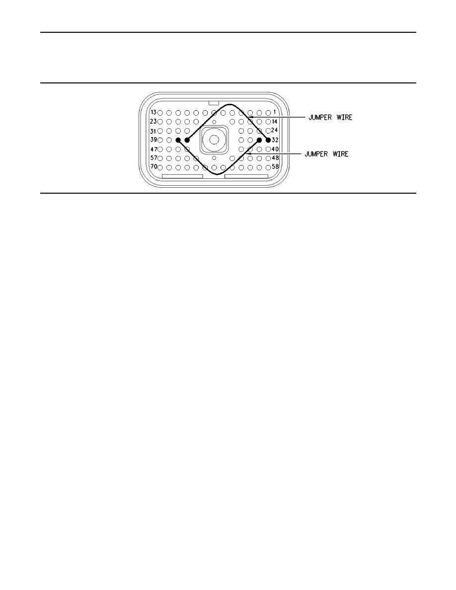
Illustration 188
Jumper wire locations for breakout T
A. Turn the ignition key switch to the OFF position.
Expected Result:
ET indicates a constant vehicle speed between
B. Fabricate two jumper wires 100 mm (4 inch) long.
80 to 96 km/h (50 to 60 mph) when the jumper wires
Crimp a Deutsch pin to both ends of the wires.
from the speedometer circuit are connected.
C. Disconnect vehicle harness connector P1 from
the ECM.
Results:
OK The ECM is operating correctly. The source
D. Connect a breakout T to ECM connector J1 and
connect P1 to the breakout T.
of the problem is either the wiring or the source
of the problem is the vehicle speed sensor.
E. Install one jumper into the breakout T in order to
connect terminal 36 (speedometer positive) to
Repair: Perform the following repair:
terminal 32 (vehicle speed in positive). Install
the other jumper into the breakout T in order to
If the sensor is damaged, replace the damaged
connect terminal 37 (speedometer negative) to
sensor or send the vehicle to the OEM dealer for
terminal 33 (vehicle speed in negative).
repairs.
Refer to Illustration 188.
Verify that any repair eliminates the problem.
F. Turn the ignition key switch to the ON position.
STOP.
Not OK Recheck the connections of the jumper
G. Connect ET to the cab data link connector.
wires. Leave the jumper wires installed in the
H. Access the "55 mph VSP/Speedometer Test" by
breakout T. Disconnect the breakout T. Proceed
Accessing the following display screens in order:
to Test Step 8.
Test Step 8. Test the ECM Vehicle Speed
"Diagnostics"
Inputs When the Test ECM is Installed.
"Diagnostic Tests"
A. Connect a test ECM and reconnect the breakout
"Special Test menu"
T.
I. Activate the test and observe the vehicle speed
B. Install one jumper into the breakout T in order to
on the vehicle speed status screen.
connect terminal 36 (speedometer positive) to
terminal 32 (vehicle speed in positive). Install
the other jumper into the breakout T in order to
connect terminal 37 (speedometer negative) to
terminal 33 (vehicle speed in negative).
|
|
Privacy Statement - Press Release - Copyright Information. - Contact Us |
