 |
|||
|
|
|||
|
Page Title:
Test Step 3. Use ET to Check the Speedometer |
|
||
| ||||||||||
|
|
 414
TM 9-2320-312-24-2
Troubleshooting Section
Test Step 3. Use ET to Check the
Speedometer.
g00723985
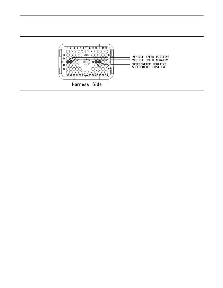
Illustration 187
Repair: Perform the following repair:
A. Inspect vehicle harness connector P1. Observe
whether connections are present to terminal
If the ECM is not connected to the OEM
36 (speedometer positive) and/or terminal 37
speedometer, send the vehicle to the OEM dealer
(speedometer negative).
for repair of the speedometer.
If there is a connection to either of the
speedometer terminals continue with the
STOP.
procedure.
No speed indicated If OEM truck wiring
B. Connect ET to the cab data link connector.
diagrams are available, trace the wiring to the
speedometer and repair the speedometer, as
C. Access the "55 mph VSP/Speedometer Test" by
required. STOP.
Accessing the following display screens in order:
Speed present, but not in range
"Diagnostics"
Repair: Perform the following diagnostic
"Diagnostic Tests"
procedure:
"Special Test menu"
Troubleshooting, "Vehicle Speed Circuit -
Calibrate"
D. Activate the test and observe the speedometer.
STOP.
Note: Some types of speedometers only require
Test Step 4. Determine the Type of
one ECM signal line to be connected to the
Vehicle Speed Circuit.
speedometer. Either of the ECM terminals can be
used for these speedometers.
A. Inspect the vehicle wiring for the type of vehicle
Refer to Illustration 187.
speed circuit that is being used.
Expected Result:
Compare the vehicle speed circuit with the
detailed circuit schematics:
The speedometer indicates 80 to 96 km/h (50 to
60 mph).
Schematic 1 Refer to Illustration 181.
Results:
Schematic 2 Refer to Illustration 182.
Yes The ECM is providing the signal for the
Schematic 3 Refer to Illustration 183.
speedometer and the wiring and the speed are
OK. Send the vehicle to the OEM dealer for repair
Schematic 4 Refer to Illustration 184.
of the speedometer. STOP.
Schematic 5 Refer to Illustration 185.
ECM not connected to speedometer
|
|
Privacy Statement - Press Release - Copyright Information. - Contact Us |
