 |
|||
|
|
|||
|
Page Title:
Test Step 2. Use ET to Check the Accelerator Pedal Position Sensor |
|
||
| ||||||||||
|
|
 407
TM 9-2320-312-24-2
Troubleshooting Section
"Special Tests"
Verify that the repair eliminates the problem.
Note: The "Transmission Style" must be programmed
STOP.
to "AT/MT/HT Option 1", "AT/MT/HT Option 2",
Test Step 2. Use ET to Check the
"AT/MT/HT Option 3", or "AT/MT/HT Option 4" for the
Accelerator Pedal Position Sensor.
"AT/MT/HT XMission Interface Test" to be available.
This will allow output 7 to control the AT/MT/HT
transmission relay.
A. Ensure that the cruise control switch is off.
D. Begin the "AT/MT/HT XMission Interface Test"
B. Connect ET to the cab data link connector.
while you listen for the solenoids to click. You
may need to be closer to the transmission in
C. Turn the ignition key switch to the ON position.
order to hear the click of the relay.
D. Use the following procedure to check the
Expected Result:
accelerator pedal position sensor:
The relay activates when the test is enabled.
a. Monitor the duty cycle of the throttle sensor
on ET. Access the display screens in the
Results:
following order:
Yes The ECM is functioning properly at this
"Service"
time. STOP.
No Proceed to Test Step 4.
"Throttle Position"
Test Step 4. Use ET to Check the ECM.
b. While the duty cycle is being monitored on ET,
depress the accelerator pedal and release
the accelerator pedal. Repeat this action
several times.
Expected Result:
The duty cycle of the accelerator pedal position
sensor is between 3 percent and 100 percent.
Results:
OK Proceed to Test Step 3.
Not OK
Repair: Perform the following diagnostic
procedure:
Troubleshooting, "Accelerator Pedal (Throttle)
Position Sensor Circuit - Test"
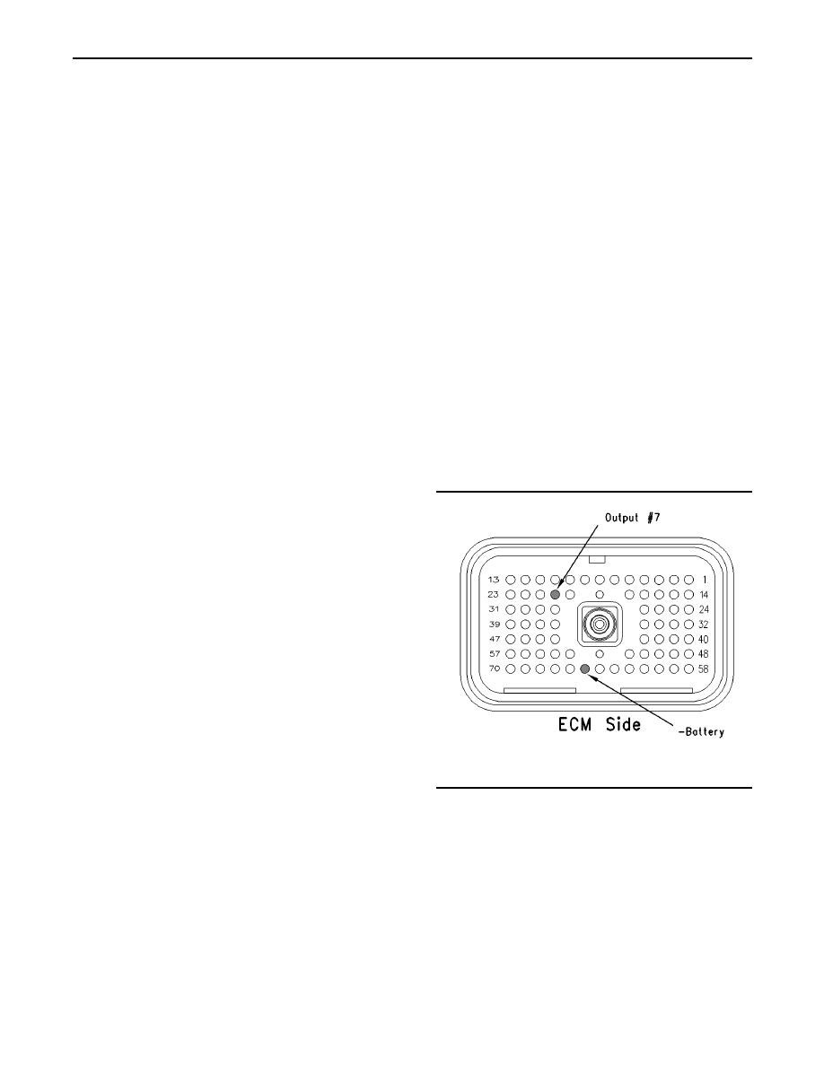
g00770060
Illustration 180
STOP.
Breakout T
Test Step 3. Use ET to Check the
A. Turn the ignition key switch to the OFF position.
B. Disconnect the ECM engine harness connector
A. Connect ET to the cab data link connector.
J1/P1.
B. Turn the ignition key switch to the ON position.
C. Connect a breakout T to the ECM connector
J1/P1.
C. Access the "AT/MT/HT XMission Interface Test"
through the following menus:
D. Connect a voltage test lamp to terminal 20
(Output 7) and terminal 65 (-Battery) of the
"Diagnostics"
breakout T.
"Diagnostic Tests"
|
|
Privacy Statement - Press Release - Copyright Information. - Contact Us |
