 |
|||
|
|
|||
|
Page Title:
Test Step 2. Inspect Electrical Connectors and Wiring |
|
||
| ||||||||||
|
|
 333
TM 9-2320-312-24-2
Troubleshooting Section
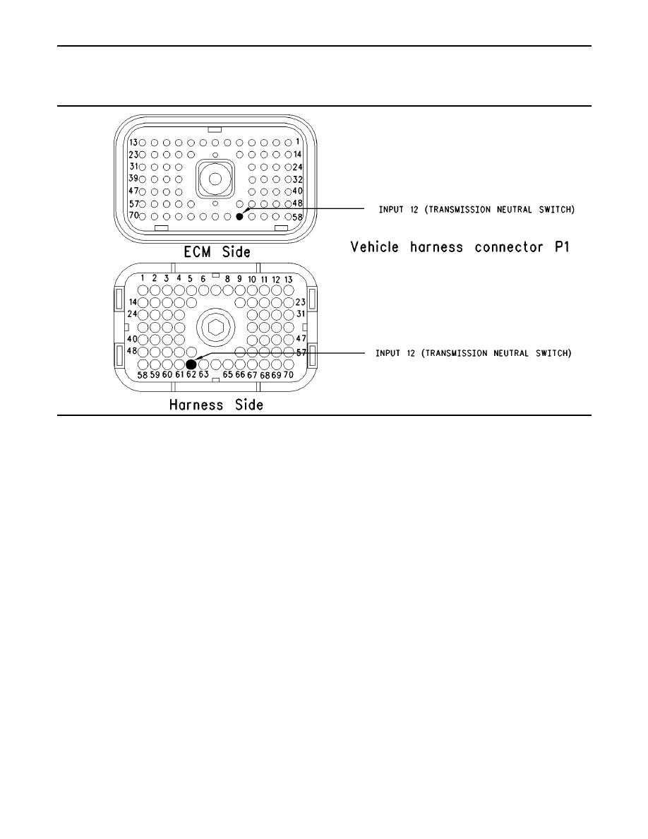
Test Step 2. Inspect Electrical Connectors
and Wiring.
g00705233
Illustration 144
Results:
A. Thoroughly inspect ECM vehicle harness
connector J1/P1, the firewall bulkhead connector
OK Proceed to Test Step 3.
and the terminals for the following switches in
the connectors:
Not OK
neutral switch (terminal 62)
Repair: Repair the connectors or wiring and/or
replace the connectors or wiring. Ensure that all
Refer to Troubleshooting, "Electrical Connectors
of the seals are properly in place and ensure that
- Inspect" for details.
the connectors are completely coupled.
B. Perform a 45 N (10 lb) pull test on each of the
Verify that the repair eliminates the problem.
wires in the ECM connector that are associated
with the switches.
STOP.
Refer to Illustration 144.
C. Check the ECM connector (allen head screw) for
the proper torque of 6.0 Nm (55 lb in).
D. Check the harness and wiring for abrasion and
pinch points from the sensor to the ECM.
Expected Result:
All connectors, pins and sockets should be
completely coupled and/or inserted and the harness
and wiring should be free of corrosion, abrasion
or pinch points.
|
|
Privacy Statement - Press Release - Copyright Information. - Contact Us |
