 |
|||
|
|
|||
|
Page Title:
Test Step 5. Check the Switch Circuit |
|
||
| ||||||||||
|
|
 231
TM 9-2320-312-24-2
Troubleshooting Section
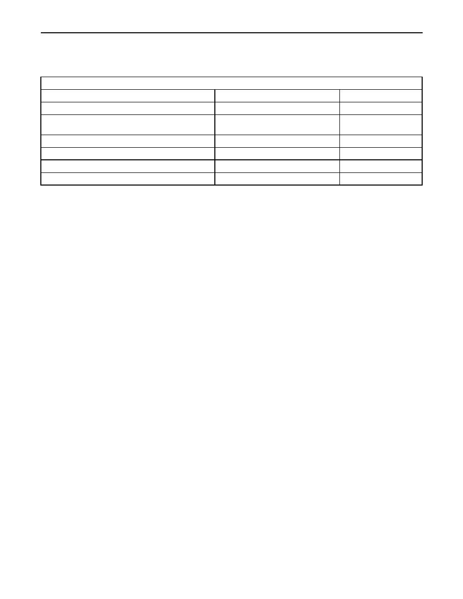
Test Step 5. Check the Switch Circuit.
Table 167
Table for Status of the Cruise Control Switch Input
Condition of Switch Circuit
Switch Status
Circuit
Terminal 59 Cruise/Idle On/Off Switch is Open.
OFF
Open
Terminal 59 Cruise/Idle On/Off Switch is connected to
ON
Shorted
terminal 5.
Set Switch Terminal 35 is Open.
OFF
Open
Set Switch Terminal 35 connected to terminal 5.
Set Switch ON
Shorted
Resume Switch (Terminal 44) is Open.
OFF
Open
Resume Switch (Terminal 44) connected to terminal 5.
Resume Switch ON
Shorted
3. Recheck the system for active diagnostic
A. Turn the ignition key switch to the OFF position.
codes.
B. Fabricate a jumper wire 100 mm (4 inch) long.
4. Repeat the test step.
Crimp a Deutsch pin to both ends of the wires.
5. If the problem is resolved with the test ECM,
C. Disconnect vehicle harness connector P1 from
reconnect the suspect ECM.
the ECM.
6. If the problem returns with the suspect ECM,
D. Connect a breakout T to ECM connector J1 and
replace the ECM.
connect P1 to the breakout T.
7. Verify that the repair eliminates the problem.
E. Install the jumper into the suspect switch socket
of the breakout T. Connect the other end of the
jumper to ECM connector P1 terminal 5 (ap
STOP.
sensor/switch sensor common) of the breakout T.
F. Turn the ignition key switch to the ON position.
G. Connect ET to the cab data link connector.
H. Access the status screen.
I. While the switch status is being monitored on
the status screen slowly remove the jumper from
terminal 5 and slowly insert the jumper from
terminal 5 (ap sensor/switch sensor common).
Refer to Table 167.
Expected Result:
The switch status changes per the information in
Table 167.
Results:
Yes The ECM is functioning properly. Proceed
to Test Step 6.
No The ECM is not functioning properly.
Repair: Perform the following repair:
1. Temporarily connect a test ECM.
|
|
Privacy Statement - Press Release - Copyright Information. - Contact Us |
