 |
|||
|
|
|||
|
Page Title:
Test Step 5. Check the A/C Compressor Clutch Switch |
|
||
| ||||||||||
|
|
 202
TM 9-2320-312-24-2
Troubleshooting Section
Result 3 Diagnostic Code 110-03 or 110-04 is
resistance between the two terminals of
logged or active.
the A/C compressor clutch switch. The A/C
compressor clutch must be engaged in order
Results:
to check the resistance.
Result 1 Proceed to Test Step 5.
Result 2 The cooling fan is ON because of a
less.
high coolant temperature.
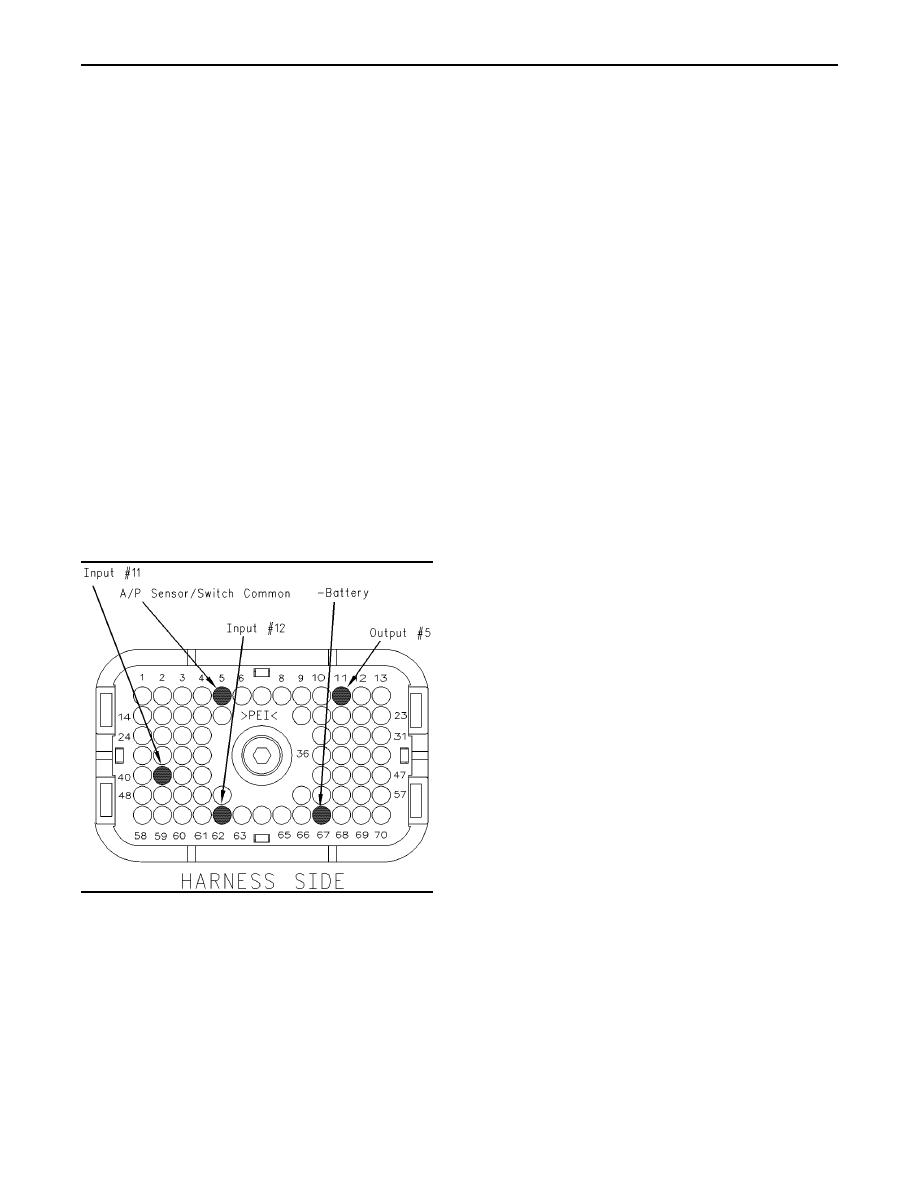
to P1:62 (Input #12), use the following steps to
Repair: Perform the following diagnostic
check the switch circuit.
procedure: Troubleshooting, "110-11 Very High
Coolant Temperature"
a. Disconnect the wire at terminal P1:62 (Input
#12).
STOP.
Result 3 The cooling fan is ON because of a
b. Connect a voltage test lamp between the wire
that was removed from terminal P1:62 and
coolant temperature sensor fault.
terminal 67 (- Battery).
Repair: Perform the following diagnostic
c. Turn the keyswitch to the ON position. The A/C
procedure: Troubleshooting, "Engine Temperature
compressor clutch must be engaged in order
Sensor Open or Short Circuit - Test"
to check the A/C compressor clutch switch.
STOP.
d. The test lamp should illuminate when the A/C
Test Step 5. Check the A/C Compressor
compressor clutch is engaged.
Clutch Switch.
Expected Result:
The circuit behaved in the manner that was
described in the instructions above.
Results:
Yes The A/C compressor clutch switch and the
wiring are electrically OK. Proceed to Test Step 6.
No
Repair: Replace the A/C compressor clutch
switch and/or the related wiring.
Verify that the repair eliminates the problem.
STOP.
Test Step 6. Use the Electronic
Service Tool to Check Inlet Manifold
Air Temperature and the Coolant
g00841499
Illustration 62
Temperature.
Pin locations on P1 connector
A. Connect the electronic service tool to the cab
A. Turn the ignition key switch to the OFF position.
data link connector.
B. Turn the ignition key switch to the ON position.
to P1:41 Input #11, use the following steps to
check the switch circuit.
a. Disconnect the wires at terminals P1:41 and
P1:5.
|
|
Privacy Statement - Press Release - Copyright Information. - Contact Us |