 |
|||
|
|
|||
|
Page Title:
Test Step 1. Inspect Electrical Connectors and Wiring |
|
||
| ||||||||||
|
|
 200
TM 9-2320-312-24-2
Troubleshooting Section
Test Step 1. Inspect Electrical Connectors
and Wiring.
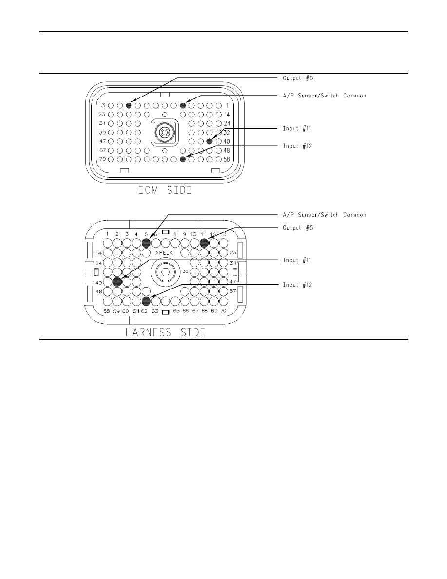
g00840659
Illustration 61
Terminal locations for the ECM connector (P1)
D. Check the harness and the wiring for abrasion
A. Thoroughly inspect the ECM vehicle harness
and pinch points from the battery to the ECM.
connector J1/P1, the connector on the clutch
Then, check from the ignition key switch to the
for the A/C compressor, the connections to the
ECM.
cooling fan solenoid, and the firewall bulkhead
connectors. Refer to Troubleshooting, "Electrical
E. Ensure that the cooling fan on the vehicle is
Connectors - Inspect" for details.
wired to the ECM. Check for wires that are
connected to terminal 11 (output 5), terminal 62
B. Perform a 45 N (10 lb) pull test on each of the
(input 12) or terminal 41 (input 11).
wires in the ECM connector that are associated
with the following connections:
Refer to Illustration 61 for terminal locations for
Cooling fan
the ECM.
circuit for the clutch of the A/C compressor
Expected Result:
All connectors, pins, and sockets are completely
C. Check the ECM connector (allen head screw) for
coupled and/or inserted, and the harness and
the proper torque of 6.0 Nm (55 lb in).
wiring should be free of corrosion, abrasion or pinch
points.
|
|
Privacy Statement - Press Release - Copyright Information. - Contact Us |
