 |
|||
|
|
|||
|
Page Title:
Valve Lash and Valve Bridge Adjustment |
|
||
| ||||||||||
|
|
 80
TM 9-2320-312-24-2
Testing and Adjusting Section
Valve Lash and Valve Bridge
a. Lightly tap the rocker arm at the top of the
adjustment screw with a soft mallet. This will
Adjustment
ensure that the lifter roller seats against the
camshaft's base circle.
b. Loosen the adjustment locknut.
c. Place the appropriate feeler gauge between
rocker arm and the valve bridge. Then, turn
the adjustment screw in a clockwise direction.
Slide the feeler gauge between the rocker arm
and the valve bridge. Continue turning the
adjustment screw until a slight drag is felt on
the feeler gauge. Remove the feeler gauge.
of 30 7 Nm (22 5 lb ft). Do not allow
the adjustment screw to turn while you are
tightening the adjustment locknut. Recheck
the valve lash after tightening the adjustment
locknut.
3. Remove the timing bolt and turn the flywheel by
360 degrees in the direction of engine rotation.
g00942236
This will put the No. 6 piston at the top center
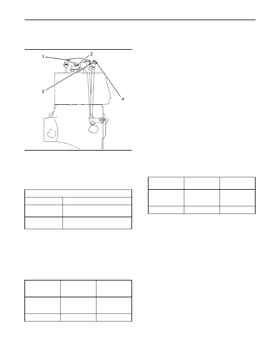
Illustration 64
position on the compression stroke. Install the
(1) Exhaust rocker arm
timing bolt in the flywheel.
(2) Inlet valve bridge
(3) Rocker arm adjustment screw locknut for the exhaust rocker
arm
Table 16
(4) Rocker arm adjustment screw for the exhaust rocker arm
TC Exhaust
Inlet Valves
Exhaust Valves
Stroke(3)
Table 14
0.38 0.08 mm
0.64 0.08 mm
Valve Lash
(0.0150 0.0031
(0.0252 0.0031
Valve Lash
Valves
Dimension of Gauge
inch)
inch)
0.38 0.08 mm
3-5-6
2-4-6
Cylinders
Inlet
(0.0150 0.0031 inch)
(3)
Position for No. 1 cylinder
0.64 0.08 mm
Exhaust
(0.0252 0.0031 inch)
4. Adjust the valve lash according to Table 16.
a. Lightly tap the rocker arm at the top of the
Adjust the valve lash while the engine is stopped.
adjustment screw with a soft mallet. This will
Use the following procedure to adjust the valves:
ensure that the lifter roller seats against the
camshaft's base circle.
1. Put the No. 1 piston at the top center position
on the compression stroke. Refer to Testing and
b. Loosen the adjustment locknut.
Adjusting, "Finding Top Center Position for No.
1 Piston".
c. Place the appropriate feeler gauge between
rocker arm and the valve bridge. Then, turn
Table 15
the adjustment screw in a clockwise direction.
TC
Slide the feeler gauge between the rocker arm
Inlet Valves
Exhaust Valves
Compression
and the valve bridge. Continue turning the
Stroke
adjustment screw until a slight drag is felt on
0.38 0.08 mm
0.64 0.08 mm
the feeler gauge. Remove the feeler gauge.
(0.0150 0.0031
(0.0252 0.0031
Valve Lash
inch)
inch)
1-2-4
1-3-5
Cylinders
2. Adjust the valve lash according to Table 15.
|
|
Privacy Statement - Press Release - Copyright Information. - Contact Us |
