 |
|||
|
|
|||
|
Page Title:
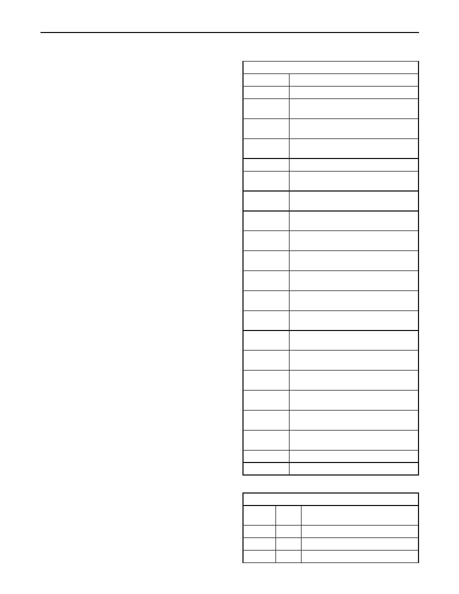
Table 1. Electrical Connectors And Functions |
|
||
| ||||||||||
|
|
 13
TM 9-2320-312-24-2
Systems Operation Section
A control component (ECM) receives the input
Table 1
signals from the input components. Electronic
Electrical Connectors And Functions
circuits inside the control component evaluate the
signals from the input components. These electronic
Connector
Function
circuits also supply electrical energy to the output
J1/P1
ECM Connector (70-Pin OEM Harness)
components of the system. The electrical energy
that is supplied to the output components is based
ECM Connector (70-Pin, Engine
J2/P2
Harness)
on predetermined combinations of input signal
values.
Coolant Temperature Sensor (2-Pin
J100/P100
Connector)
An output component is one that is operated by
Inlet Manifold Air Temperature Sensor
a control module. The output component receives
J103/P103
(2-Pin Connector)
electrical energy from the control group. The output
component uses that electrical energy in one of
J200/P200
Boost Pressure Sensor (3-Pin Connector)
two ways. The output component can use that
Atmospheric Pressure Sensor (3-Pin
electrical energy in order to perform work. The
J203/P203
Connector)
output component can use that electrical energy in
order to provide information.
Injection Actuation Pressure Sensor
J204/P204
(3-Pin Connector)
As an example, a moving solenoid plunger will
Injection Solenoid Harness (12-Pin
perform work. By performing work, the component
J300/P300
Connector)
has functioned in order to regulate the vehicle.
No. 1 Unit Injector Solenoid(2-Pin
J301/P301
As an example, a dash panel light or an alarm will
Connector)
provide information to the operator of the vehicle.
No. 2 Unit Injector Solenoid (2-Pin
J302/P302
Connector)
These electronic components provide the ability
No. 3 Unit Injector Solenoid (2-Pin
to electronically control the engine operation.
J303/P303
Connector)
Engines with electronic controls offer the following
advantages:
No. 4 Unit Injector Solenoid (2-Pin
J304/P304
Connector)
Improvement in performance
No. 5 Unit Injector Solenoid (2-Pin
J305/P305
Connector)
Improvement in fuel consumption
No. 6 Unit Injector Solenoid (2-Pin
J306/P306
Reduction in emissions levels
Connector)
Engine Timing Calibration Probe (2-Pin
J400/P400
Connector)
Top Camshaft Speed/Timing Sensor
J401/P401
(2-Pin Connector)
Bottom Camshaft Speed/Timing Sensor
J402/P402
(2-Pin Connector)
Accelerator Pedal Position Sensor (3-Pin
J403/P403
Connector)
Injection Actuation Pressure Control
J500/P500
Valve (2-Pin Connector)
J501/P501
Air Inlet Heater Relay (2-Pin Connector)
J648/P648
Air Inlet Heater Lamp (2-Pin Connector)
Table 2
Diagnostic Flash Codes
Flash
PID-FMI
Description of Code
Code
1-11
72
Cylinder 1 Fault
2-11
72
Cylinder 2 Fault
3-11
73
Cylinder 3 Fault
(continued)
|
|
Privacy Statement - Press Release - Copyright Information. - Contact Us |