 |
|||
|
|
|||
|
|
|||
| ||||||||||
|
|
 TM 9-2320-312-24-1
STEERING GEAR, DRAG LINK, AND PITMAN ARM REPLACEMENT - CONTINUED
0146 00
INSTALLATION - CONTINUED
3.
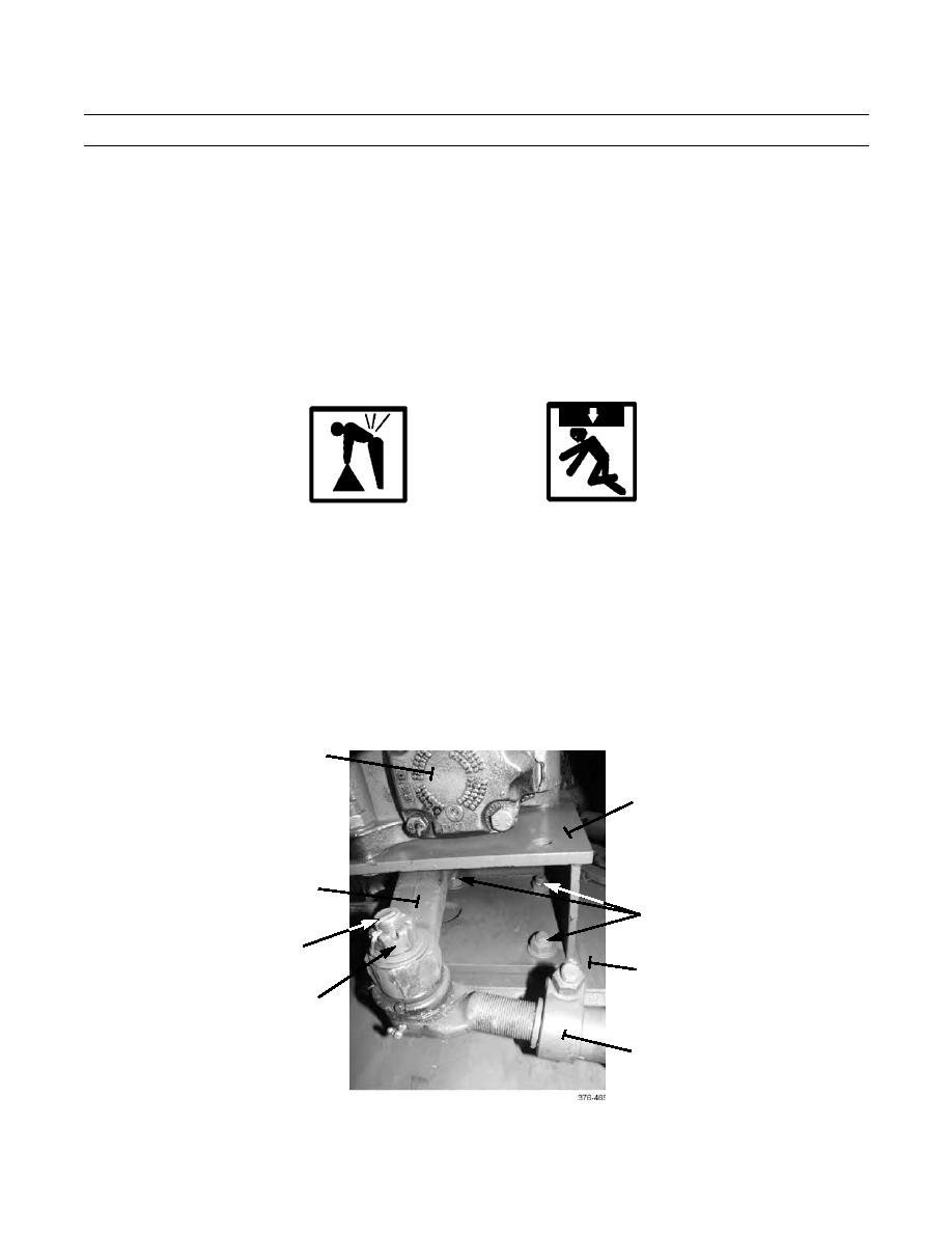
Install pitman arm (17) to steering gear (10) (Group 110 Commercial Service Manuals).
NOTE
If installing a new drag link, length of drag link should be adjusted to 34 in (86.36 cm) from center-to-center
of ball joint ends.
4.
Connect drag link (1) to pitman arm (17) with castle nut (15). Tighten castle nut to 250 lb-ft (339 Nm). Install new cotter
pin (16).
WARNING
Use extreme caution when handling heavy parts. Provide adequate support and use assistance during proce-
dure. Ensure that any lifting device used is in good condition and of suitable load capacity. Keep clear of
heavy parts supported only by lifting device. Failure to follow this warning may result in injury or death to
personnel.
5.
Place steering gear bracket (11) with attached steering gear (10), drag link (1), and pitman arm (17) centered on blocks
of wood and hydraulic floor jack. Raise floor jack and position steering gear bracket against left frame rail (14).
6.
Install steering gear bracket (11) to left frame rail (14) with four bolts (13) and nuts (12). Tighten nuts to 280 lb-ft (380
Nm).
10
11
17
12,13
16
14
15
1
0146 00-6
|
|
Privacy Statement - Press Release - Copyright Information. - Contact Us |
