 |
|||
|
|
|||
|
|
|||
| ||||||||||
|
|
 TM 9-2320-312-24-1
ELECTRICAL GENERAL MAINTENANCE INSTRUCTIONS - CONTINUED
0120 00
ELECTRICAL GROUND POINTS
NOTE
Good electrical ground points are essential for the proper functioning of the electrical system. Ground points
on electrical components and the frame of vehicle must be maintained in a clean and secure condition to
minimize electrical problems.
1.
Remove nut, locknut, lockwasher, screw etc. connecting ground wire or ground cable to ground point on electrical com-
ponent or threaded stud on vehicle frame.
2.
If necessary, clean dirt from ring terminal, surface of electrical component, ground point, and all mounting hardware
with detergent, water, and a scrub brush.
3.
Remove any corrosion or rust with a wire brush and abrasive cloth.
4.
Replace defective mounting hardware. Replace defective ring terminal. (Refer to Ring Terminal Repair).
5.
Install ground wire or ground cable to ground point with mounting hardware and tighten securely.
6.
Apply one or more coats of insulating varnish to ground connections.
MULTIMETER USAGE
General. The digital multimeter is used to troubleshoot the electrical system of the vehicle. The multimeter's ohms
1.
scale is used to test for continuity, shorts, and resistance and the voltmeter scale is used to test voltage levels at any point
in the electrical system.
2.
Continuity Tests. Continuity tests are performed to check for breaks in a circuit (such as a fuse, switch, light bulb or
electrical cable).
NOTE
If digital readout will not zero properly, replace batteries and repeat zeroing procedure. If digital readout will
not zero after batteries have been replaced, notify your supervisor.
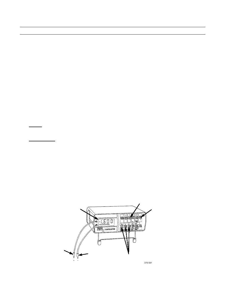
a.
Zero the Multimeter.
(1)
Set multimeter ON/OFF switch (22) to ON position.
(2)
Press OHMS FUNCTION switch (21).
(3)
Press LOWEST VOLTAGE/OHMS selector switch (23).
(4)
Touch black and red probes (24 and 25) together and check for a zero reading on digital readout (20).
21
20
22
25
24
23
0120 00-4
|
|
Privacy Statement - Press Release - Copyright Information. - Contact Us |
