 |
|||
|
|
|||
|
|
|||
| ||||||||||
|
|
 TM 9-2320-312-24-1
FIFTH WHEEL LOCK CONTROL VALVE REPLACEMENT - CONTINUED
0075 00
REMOVAL
1.
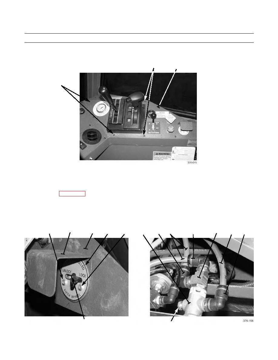
Remove eight screws (1) and lift right-side instrument panel (2) away from instrument panel frame.
1
2
1
NOTE
Tag air lines and note position of fifth wheel lock control valve and all fittings to ensure correct installa-
tion.
Refer to WP 0066 00 for instructions on removing and installing air lines to push-in fittings.
2.
Remove two screws (3), plate (5), guard (4), and valve (6) from right-side instrument panel (2).
3.
Disconnect three air lines (8) from three elbows (7).
4.
Remove three elbows (7), tee (9), and plug (10) from valve (6).
4
9
3
2
7
3
7
6
5
7
8
8
6
10
0075 00-2
|
|
Privacy Statement - Press Release - Copyright Information. - Contact Us |