 |
|||
|
|
|||
|
|
|||
| ||||||||||
|
|
 TM 9-2320-312-24-1
CHARGE AIR COOLING LINES REPLACEMENT - CONTINUED
0016 00
REMOVAL - CONTINUED
NOTE
Perform steps 3 and 4 for charge air cooling lines at left side of engine.
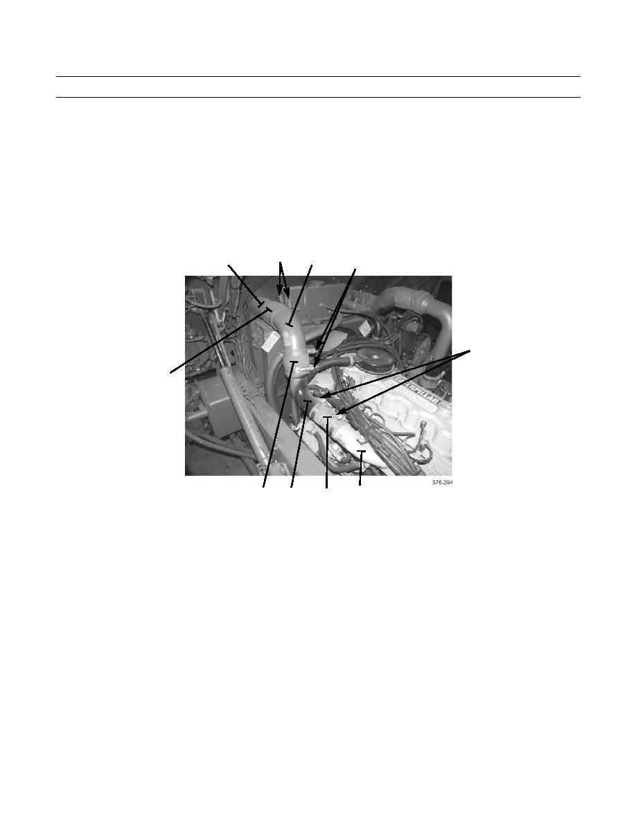
3.
Starting at charge air cooler (4), loosen and remove four hose clamps (10) and two hose clamps (12).
4.
Remove hose (17), elbow (11), hose (16), adapter (15), and small hose (14) from between charge air cooler (4) and
engine intake manifold (13).
10
4
11
10
12
17
13
16
15
14
INSTALLATION
NOTE
Perform steps 1 and 2 for charge air cooling lines at left side of engine.
Use a solution of detergent and water as necessary to lubricate hoses for ease in installation.
1.
Position small hose (14), adapter (15), hose (16), elbow (11), and hose (17) between engine intake manifold (13) and
charge air cooler (4).
2.
Install two hose clamps (12) and four hose clamps (10). Tighten clamps to 72 lb-in (8 Nm).
NOTE
Perform steps 3 and 4 for charge air cooling lines at right side of engine.
3.
Position hose (5), tube (3), hose (6), elbow (1), and small hose (7) between charge air cooler (4) and turbocharger (8).
4.
Install four hose clamps (2) and two hose clamps (9). Tighten clamps to 72 lb-in (8 Nm).
0016 00-2
|
|
Privacy Statement - Press Release - Copyright Information. - Contact Us |
