 |
|||
|
|
|||
|
Page Title:
FUEL SYSTEM - CONTINUED |
|
||
| ||||||||||
|
|
 TM 9-2320-312-24-1
THEORY OF OPERATION - CONTINUED
0003 00
FUEL SYSTEM - CONTINUED
3.
The high-pressure fuel system consists of the following:
a.
HEUI injectors at each cylinder;
b.
hydraulic pump--pressurizes a portion of the engine lubricating oil to the injection actuation pressure that is
required in order to power the HEUI injectors;
c. Injection Actuation Pressure (IAP) control valve--a high-precision valve that controls actuation pressure; and
d. IAP sensor--monitors actuation pressure and communicates this information to the engine ECM.
4.
The 40-micron primary fuel filter also serves as a fuel/water separator. A hand priming pump is mounted to the second-
ary fuel filter.
EXHAUST SYSTEM
The exhaust system removes exhaust gases from the engine through the exhaust manifold. The gasses flow into exhaust pipes
and a muffler to the atmosphere above and to the right side of the cab.
COOLING SYSTEM
1.
The cooling system consists of a circulating pump, a standard modulating water temperature regulator (thermostat), a
transmission oil cooler, charge air cooler, radiator, and an air-actuated engine fan clutch.
2.
The cooling system cools the engine by circulating ethylene glycol-based coolant through the engine and radiator. Cool-
ant is also directed to cool the engine air compressor.
ELECTRICAL SYSTEM
1.
The electrical system consists of two 12-volt batteries, 40kJ capacitor and capacitor relay, 100-amp alternator, and volt-
age regulator that supply power to the engine 24-volt starter and trailer receptacle connectors. Vehicles equipped with
arctic heater use four 12-volt batteries and 40kJ and 120kJ capacitors.
2.
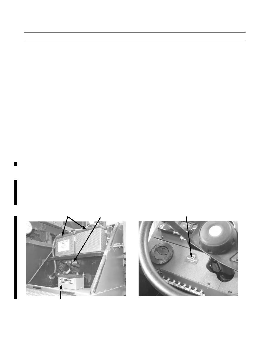
The KAPower capacitor is an electrical storage device designed as a backup power source to start the engine if batteries
are low or dead. It is installed in parallel with the vehicle's starting batteries. It derives its power from the batteries or
vehicle charging system and discharges this power when needed. In the event of discharged or low battery power, vehi-
cle may be started with the isolated available power stored within the capacitor(s), by using the emergency start switch
on the instrument panel.
CAPACITOR
BATTERIES
EMERGENCY START SWITCH
376-3001
376-3000
CAPACITOR
3.
The yard tractor is equipped with commercial 12-volt lights to include the following: headlights, marker clearance
lights, beacon warning light, floodlights, taillights, and backup light.
0003 00-2
Change 1
|
|
Privacy Statement - Press Release - Copyright Information. - Contact Us |
