|
| |
TM 9-2320-304-14&P
4-170.5
Organizational Maintenance Instructions (Cont)
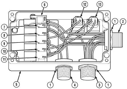
a. Removal.
NOTE
This procedure shows removal of CHU wiring for CHU control box. Only remove wiring
required to complete task.
(1)
Remove three nuts (1) from connectors MC82A (2), MC82B (3), and MC185A (4) on control
box (5).
NOTE
·
Disconnect only wires required to complete task. Refer to Table 4-4.1, CHU Control
Box Wiring, for specific control box wiring replacement.
·
Tag and mark wires prior to removal.
Table 4-4.1 CHU Control Box Wiring
Cable No.
Color
From
To
1435
BLK
10 Pin Connector A (MC185A) (4)
17 Pin Connector K (MC82A) (2)
17 Pin Connector K (MC82B) (3)
1474
BLK
10 Pin Connector B (MC185A) (4)
17 Pin Connector F (MC82A) (2)
17 Pin Connector F (MC82B) (3)
Relay R54/Terminal 3 (10)
1466B
BLK
10 Pin Connector C (MC185A) (4)
Relay R53/Terminal 3 (9)
1466C
BLK
Relay R53/Terminal 4
Relay R54/Terminal 1 (13)
1495
BLK
10 Pin Connector D (MC185A) (4)
1435
BLK
10 Pin Connector E (MC185A) (4)
Change 1
|