 |
|||
|
|
|||
|
|
|||
| ||||||||||
|
|
 TM 9-2320-303-24-2
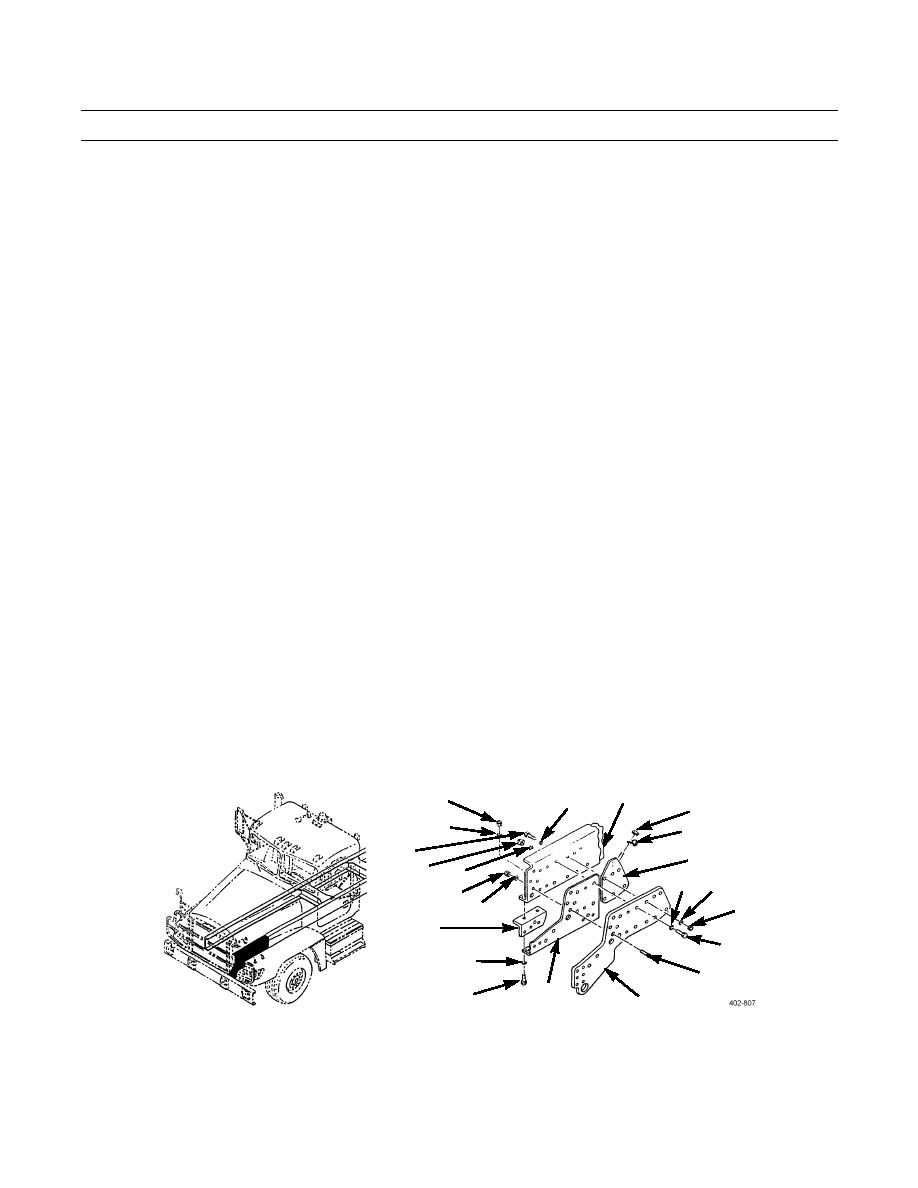
FRAME RAIL EXTENSION AND REINFORCEMENT REPLACEMENT - CONTINUED
0278 00
REMOVAL
NOTE
Steps 1 through 9 are for left side only.
Steps 10 through 16 are for right side only.
1.
Remove nut (5) and clamp (6) from power steering reservoir plate (3).
NOTE
Note position of capscrews prior to removal to aid in installation.
2.
Remove six nuts (8), six washers (7), six capscrews (20), and six washers (1).
3.
Remove power steering reservoir plate (3) from between frame rail reinforcement (11) and frame rail (2).
4.
Install any two washers (1), two capscrews (20), two washers (7), and two nuts (8) hand-tight in frame rail reinforce-
ment (11) and frame rail (2).
5.
Remove two nuts (17), two washers (16), and two screws (10).
6.
Remove three nuts (19), three washers (18), three capscrews (9), and three washers (4).
7.
Remove frame rail extension (12) from between frame rail reinforcement (11) and frame rail (2).
WARNING
Frame rail reinforcement weighs 100 lb (45.4 kg). Use minimum of three personnel to remove or install
parts from or on frame rail reinforcement. Failure to do so could result in injury to personnel.
8.
With two personnel holding frame rail reinforcement (11), remove two nuts (8), two washers (7), two capscrews (20),
two washers (1), and frame rail reinforcement.
NOTE
In steps 9 and 10, note position of capscrews prior to removal to aid in installation.
9.
Remove two nuts (22), two washers (21), two capscrews (13), two washers (14), and stiffener (15).
2
22
1
5
21
6
20
3
19
18
4
7
17
16
8
15
9
14
10
12
13
11
10.
Remove five nuts (23), five washers (38), five capscrews (28), five washers (27), and bracket (40). Set bracket aside.
11.
Remove transmission cooler mounting plate (24) from between frame rail reinforcement (36) and frame rail (26).
0278 00-2
|
|
Privacy Statement - Press Release - Copyright Information. - Contact Us |
