 |
|||
|
|
|||
|
Page Title:
DIFFERENTIAL CARRIER ASSEMBLY - CONTINUED |
|
||
| ||||||||||
|
|
 TM 9-2320-303-24-2
REAR-REAR AXLE DIFFERENTIAL CARRIER REPAIR - CONTINUED
0259 00
DIFFERENTIAL CARRIER ASSEMBLY - CONTINUED
(3)
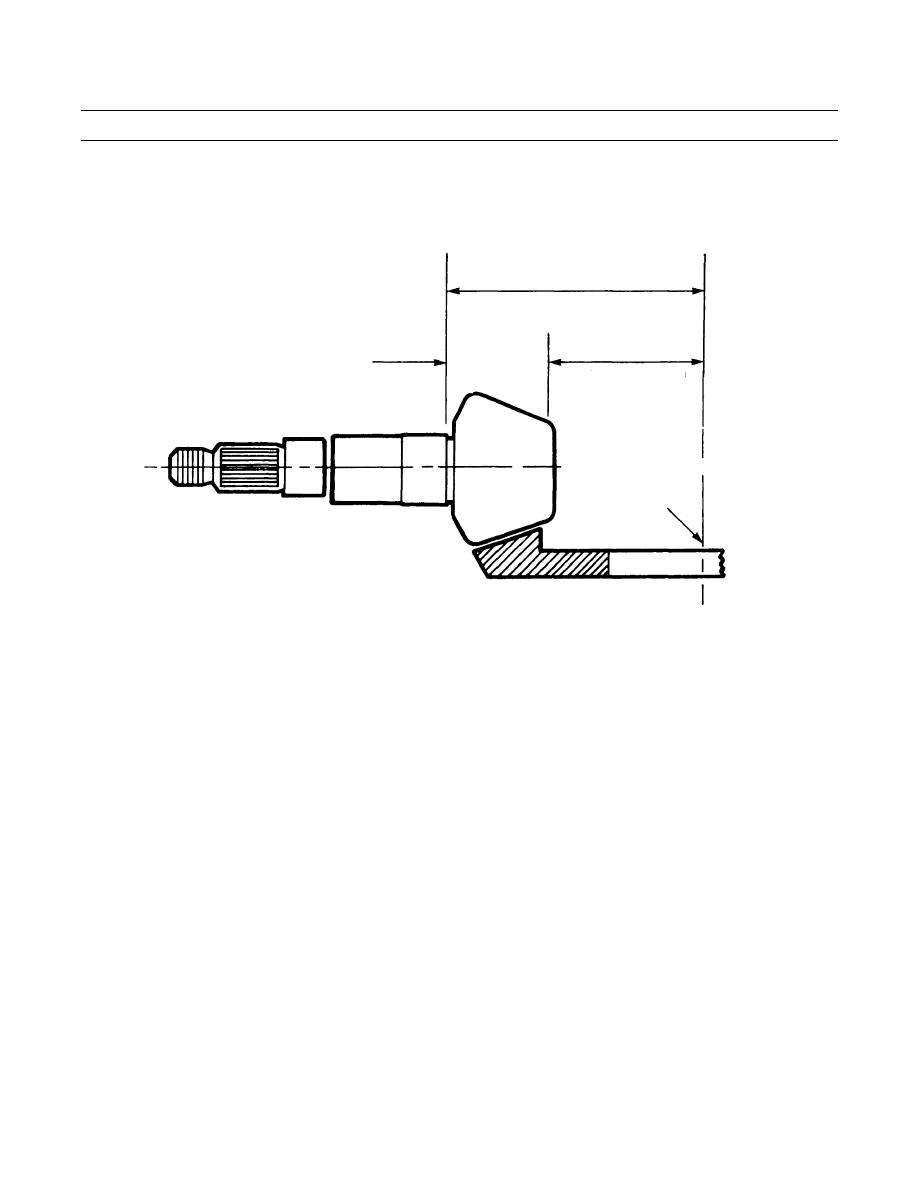
Make a note of the nominal pinion mounting distance dimension stamped on the pinion nose (fig. 2).
NOMINAL PINION
MOUNTING DISTANCE (7.875)
(STAMPED ON NOSE OF PINION)
NOMINAL
MEASURED
PINION
DIMENSION
HEAD
(USE WITH PINION
DIMENSION
SETTING GAGE)
CENTERLINE OF GEAR
& DIFFERENTIAL
BEARING BORES
NOMINAL PINION
MEASURED
MINUS
MOUNTING DISTANCE
=
NOMINAL DIMENSION
PINION HEAD
7.875
DIMENSION
402-711
Figure 2. Establish Nominal Dimension.
(4)
Measure the length of the pinion head. Measure this distance from the nose to the bearing shoulder using a
3-4 in. micrometer or vernier.
(5)
Mark the spot on the pinion nose from which the head length measurement was taken. Later, when using
the pinion setting gage, measure to the same spot.
(6)
Subtract the measured pinion head length from the nominal pinion mounting distance noted in step (3).
The remainder is the nominal or gaging distance used for calculations when using the pinion setting gage.
See figure 52 for the formula.
(7)
Continue with procedures using the calculated nominal (gaging) distance and the plus or minus PC varia-
tion.
0259 00-7
|
|
Privacy Statement - Press Release - Copyright Information. - Contact Us |
