 |
|||
|
|
|||
|
|
|||
| ||||||||||
|
|
 TM 9-2320-303-24-2
TRANSMISSION OVERHAUL - CONTINUED
0248 00
MODULE OVERHAUL - CONTINUED
Main Shaft Module Disassembly
1.
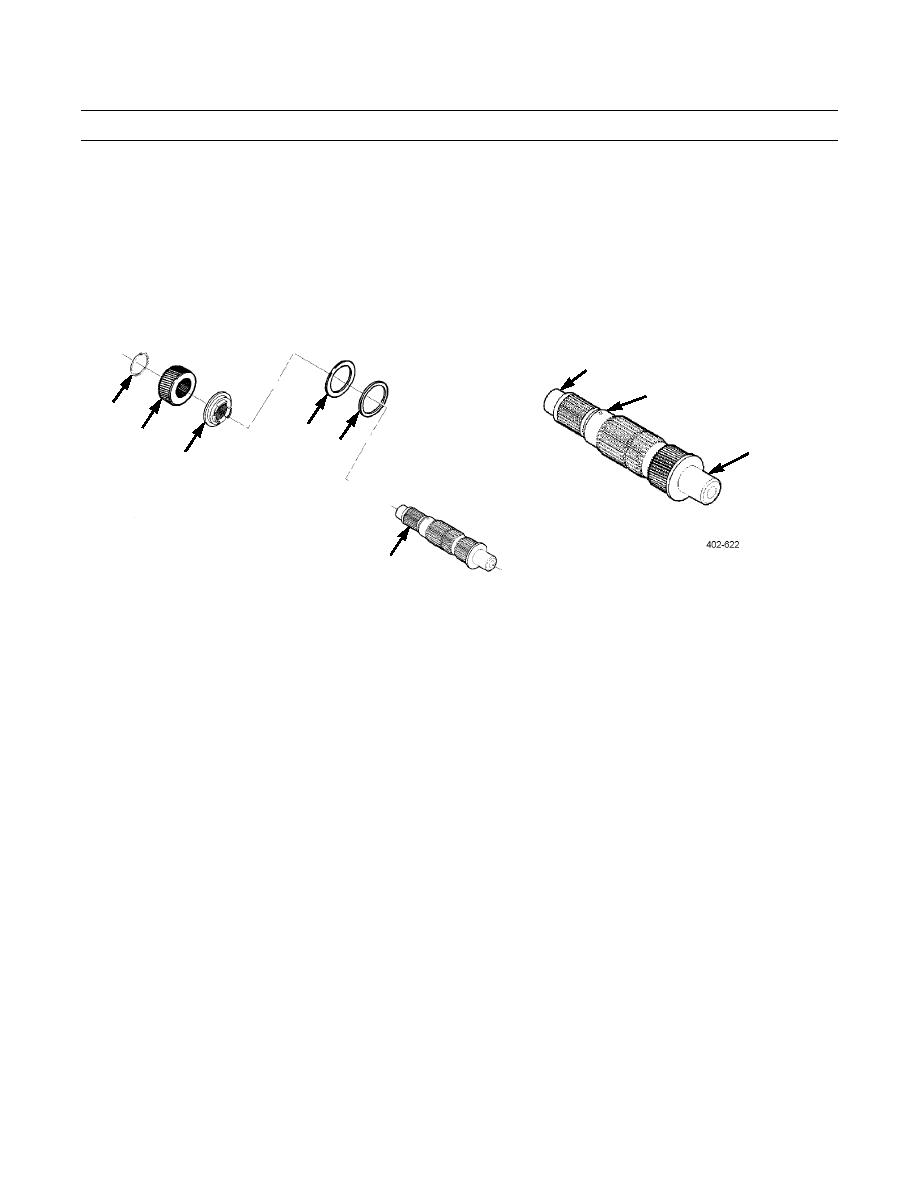
Remove external spiral retaining ring (1) and P2 sun gear (2) from main shaft (6).
2.
Remove bearing spacer (3), thrust bearing (5), and selective shim (4) from main shaft (6).
3.
Inspect and measure main shaft (6). Inspect for evidence of wear, chipped or cracked splines or teeth. Measure main
shaft in accordance with Table 2, Wear Limits Data, located at the end of this work package.
35.92 mm
(1.414 in)
52.98 mm
(2.085 in)
1
4
35.92 mm
2
(1.414 in)
5
3
6
Main Shaft Module Assembly
NOTE
Do not install thrust bearing (5) and selective shim (4) until final transmission assembly. Measurement for
selective shim is performed during final buildup.
1.
Install bearing spacer (3) on main shaft (6).
2.
Install P2 sun gear (2) and external spiral retaining ring (1) on main shaft (6).
P1 Planetary Module Disassembly
1.
Remove internal retaining ring (1) from P2 planetary ring gear (5) and remove P2 planetary ring gear from planetary
module (2).
2.
Check P1 planetary carrier assembly (3) for pinion end play. Pinion end play must not exceed 0.037 in (0.94 m). Check
all six pinion gears.
3.
Remove retaining ring (13) and indexing ring (12).
4.
Remove six pinion spindles (11) from P1 planetary carrier (3).
5.
Remove pinion gear (9), thrust washers (7 and 10), and two bearing assemblies (8) from side of P1 planetary carrier (3).
Repeat procedure for remaining pinion gears.
6.
Measure thickness and step wear of thrust washers (7 and 10). Minimum thrust washer thickness allowed is 0.055 in
(1.40 mm). Maximum step wear allowed is 0.005 in (0.12 mm).
7.
Remove thrust bearing (4) from P1 planetary carrier (3).
0248 00-32
|
|
Privacy Statement - Press Release - Copyright Information. - Contact Us |