 |
|||
|
|
|||
|
Page Title:
Front Support and Charging Oil Pump Module Disassembly - Continued |
|
||
| ||||||||||
|
|
 TM 9-2320-303-24-2
TRANSMISSION OVERHAUL - CONTINUED
0248 00
MODULE OVERHAUL - CONTINUED
Front Support and Charging Oil Pump Module Disassembly - Continued
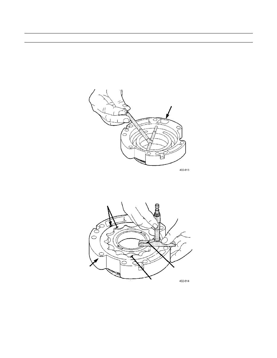
5.
Measure gear cavity diameter of pump housing (1). Maximum depth allowed is 5.915 in (150.25 mm).
1
MAX ID OF
GEAR CAVITY
150.25 mm (5.915 in)
6.
Install gear set (2) into pump housing (1). Measure pump gear side clearance of both gears. Maximum allowable clear-
ance is 0.004 in (0.10 mm).
2
DRIVE
1
GEAR
MAX SIDE
DRIVEN GEAR
CLEARANCE
0.10 mm (0.004 in)
0248 00-18
|
|
Privacy Statement - Press Release - Copyright Information. - Contact Us |
