 |
|||
|
|
|||
|
|
|||
| ||||||||||
|
|
 TM 9-2320-303-24-2
ALTERNATOR REPAIR - CONTINUED
0233 00
TESTING - CONTINUED
4.
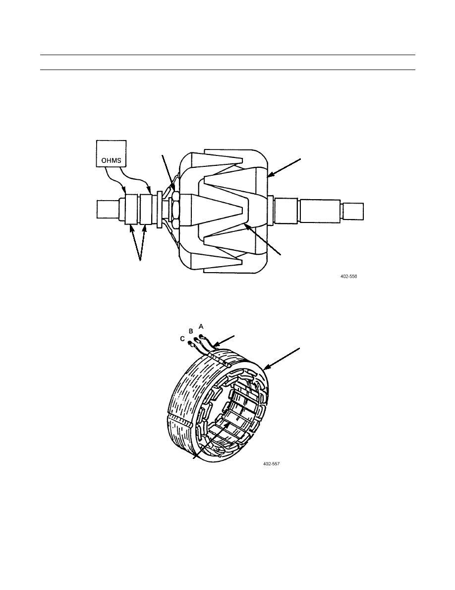
Test rotor assembly (32) as follows:
a. With ohmmeter connected between nut (37) and either of two slip rings (33), no reading should be obtained. If any
reading is obtained, rotor coil (38) is grounded and rotor assembly (32) must be disassembled to repair short.
b.
Check rotor coil (38) resistance by connecting ohmmeter across both slip rings (33). Resistance should be 9.6-10.4
ohms. If resistance is outside limits, replace rotor coil.
37
32
38
33
5.
Test stator (14) as follows:
a. Connect one ohmmeter lead to bare metal surface on stator lamination (40). Connect other lead to each of three sta-
tor leads (39) terminals. High resistance reading should be obtained each time. If there is no reading or ohmmeter
reads zero, replace stator.
39
14
40
b.
Connect ohmmeter leads to stator leads (39) terminals as follows and note each reading:
(1)
A and B
(2)
A and C
(3)
B and C
c.
Each measurement in step b should be approximately equal. If difference is great between any two readings,
replace stator (14).
0233 00-5
|
|
Privacy Statement - Press Release - Copyright Information. - Contact Us |