 |
|||
|
|
|||
|
Page Title:
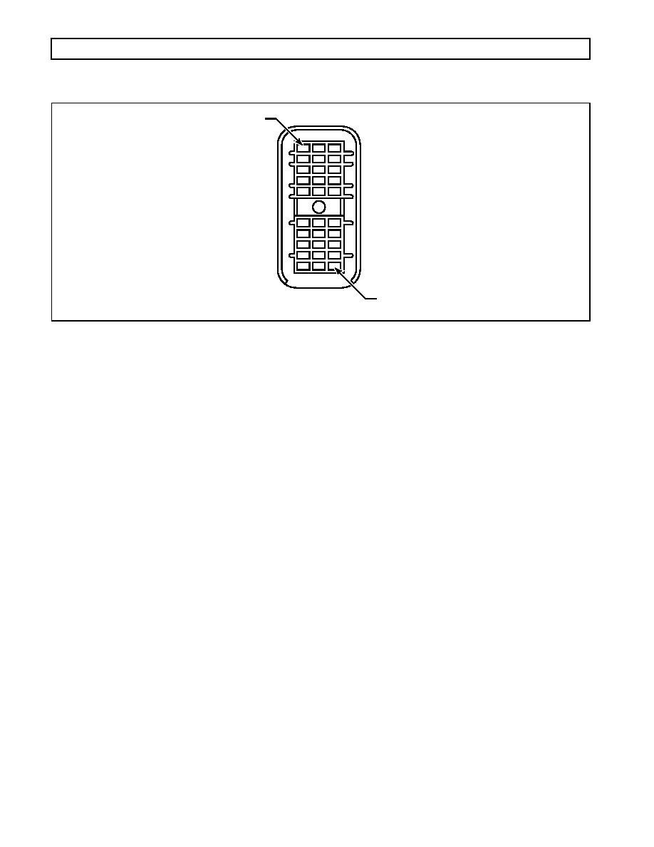
Figure D15. VIM Connector (Harness) |
|
||
| ||||||||||
|
|
 WTEC III ELECTRONIC CONTROLS TROUBLESHOOTING MANUAL
APPENDIX D -- WIRE/CONNECTOR CHART
A1
K3
V01240
Figure D15. VIM Connector (Harness)
VIM CONNECTOR (HARNESS 30-WAY)
Terminal No.
Color
Wire No.
Description
Termination Point(s)*
A1
Blue
313NO
Reverse Warning Relay -- Normally Open
A2
Yellow
314CM
Output Wire 114 Relay -- Common
A3
Blue
314NO
Output Wire 114 Relay -- Normally Open
B1
Yellow
313CM
Reverse Warning Relay -- Common
B2
Green
314NC
Output Wire 114 Relay -- Normally Closed
B3
Reserved
C1
Orange
346
Ignition Power
C2
Green
312NC
Output Wire 112 Relay -- Normally Closed
C3
Reserved
D1
Green
325NC
Output Wire 125 Relay -- Normally Closed
D2
Green
332NC
Output Wire 132 Relay -- Normally Closed
D3
Reserved
E1
Yellow
325CM
Output Wire 125 Relay -- Common
E2
Yellow
332CM
Output Wire 132 Relay -- Common
E3
Blue
332NO
Output Wire 132 Relay -- Normally Open
F1
Blue
323NO
Neutral Start Relay -- Normally Open
F2
Yellow
312CM
Output Wire 112 Relay -- Common
F3
Blue
312NO
Output Wire 112 Relay -- Normally Open
G1
Yellow
323CM
Neutral Start Relay -- Common
G2
Reserved
G3
Reserved
H1
Reserved
H2
White
357UF
Speedometer -- Unfiltered
H3
Reserved
J1
Pink
336A
Battery Power
J2
Pink
336C
Battery Power
J3
Reserved
K1
Gray
343A
Battery Ground
K2
Gray
343C
Battery Ground
K3
Reserved
* Termination Points are determined by OEM electrical system design.
0021 00158
|
|
Privacy Statement - Press Release - Copyright Information. - Contact Us |
