 |
|||
|
|
|||
|
Page Title:
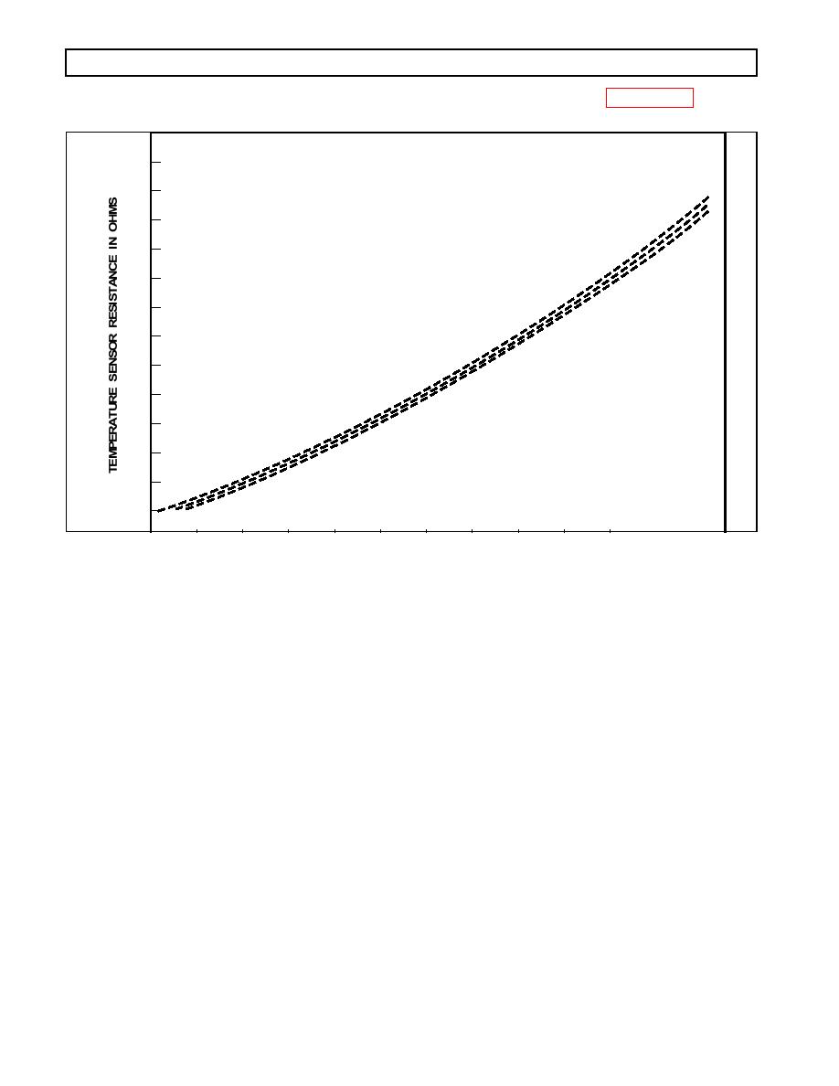
Figure 512. Temperature Sensor Chart |
|
||
| ||||||||||
|
|
 WTEC III ELECTRONIC CONTROLS TROUBLESHOOTING MANUAL
TEMPERATURE VS. RESISTANCE
TEMP C
TEMP F
OHMS
2900
-58
525
-50
-40
577
-40
7.0C
2700
-22
632
-30
-4
691
-20
14
754
-10
2500
32
820
0
50
889
10
2300
5.0C
68
962
20
86
1039
30
1118
104
40
2100
1202
122
50
1288
140
60
4.0C
1900
1379
158
70
1472
176
80
1700
1569
194
90
3.0C
1670
100
212
1774
110
230
1500
1882
120
248
2.0C
1993
266
130
1300
2107
284
140
2225
150
302
1100
361
2628
183
1.6C
900
LOW PT
700
3.0C
SUMP TEMPERATURE IN F
500
4
32
68
104
140
176
212
248
284
320
356
Figure 512. Temperature Sensor Chart
3. Disconnect the external harness at the transmission. Check the connectors and terminals for dirt,
corrosion, or damage. Clean or replace as necessary.
4. Check the sensor wires in the external harness for opens (code 33 23), shorts between wires, or
shorts-to-ground (code 33 12 -- refer to Section 4). If wiring problems are found, isolate and re-
pair.
5. If no harness problems are found, check the feedthrough harness for damage. If the feedthrough
harness connector is satisfactory, drain the fluid and remove the control module. Check for chafing
of the sensor wires, especially near the separator plate. Eliminate the chafe point. If no chafe point
is found, replace the sensor.
6. If the problem recurs, use a spare wire, if available, or provide a new wire (St. Clair P/N 200153
may be used for this purpose) for the temperature sensor circuit.
7. If the condition persists, replace the ECU. If replacing the ECU corrects the problem, reinstall the
original (bad) ECU to confirm that the problem is in the ECU. If the original ECU now works, in-
spect the ECU connectors for any corrosion or damage which may cause an intermittent condition.
If the original problem recurs, reinstall the replacement ECU.
0021 0078
|
|
Privacy Statement - Press Release - Copyright Information. - Contact Us |