 |
|||
|
|
|||
|
|
|||
| ||||||||||
|
|
 TM 9-2320-302-20-2
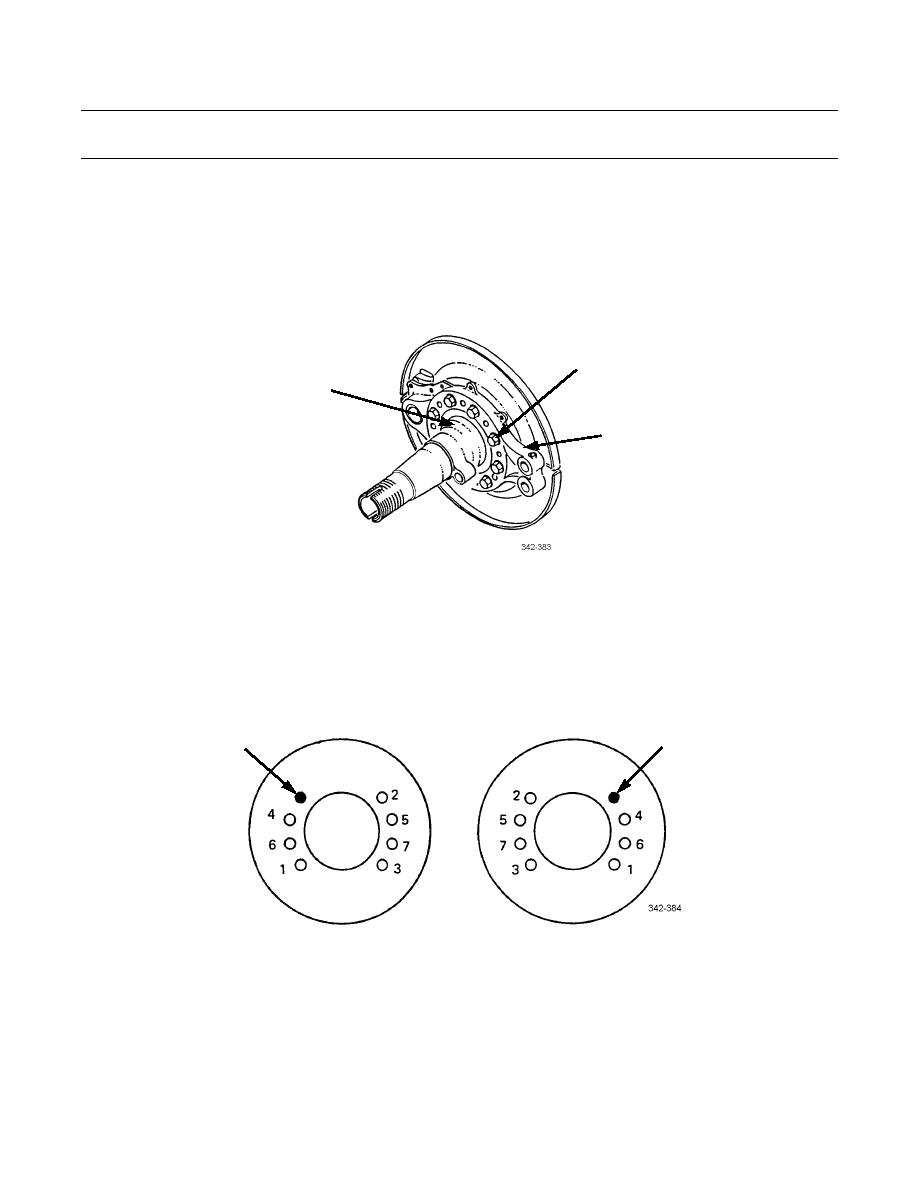
REAR BRAKE SPIDER AND BRAKE CHAMBER
BRACKET REPLACEMENT - CONTINUED
0178 00
REMOVAL - CONTINUED
NOTE
Matchmark spider position prior to removal from axle flange to aid in installation.
3.
Remove eight locknuts (8), washers (9), flange bolts (10), washers (11), and spider (6) from axle flange (7). Discard
locknuts.
8,9,10,11
7
6
INSTALLATION
NOTE
Position spider as matchmarked during removal.
1.
Install spider (6) on axle flange (7) with eight washers (11), flange bolts (10), washers (9), and new locknuts (8). Tighten
locknuts to 150-175 lb-ft (203-237 Nm) in sequence shown.
OPEN FOR
OPEN FOR
ABS SENSOR
ABS SENSOR
RIGHT-REAR SIDE
LEFT-REAR SIDE
2.
Apply a light coat of GAA grease to two bushings (2) and new seals (1).
NOTE
Install bushings with label ends facing each other. Install bushings to a depth of 3/8 in (9.5 mm) from each
end. Install each seal with lip facing slack adjuster.
3.
Install two bushings (2) and seals (1) on spider (6).
0178 00-2
|
|
Privacy Statement - Press Release - Copyright Information. - Contact Us |
