 |
|||
|
|
|||
|
|
|||
| ||||||||||
|
|
 TM 9-2320-303-24
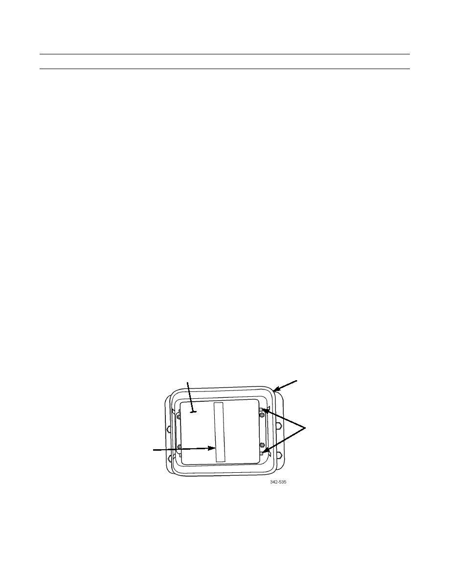
COLLISION WARNING SYSTEM (CWS) ANTENNA ALIGNMENT - CONTINUED
0134 00
HORIZONTAL ALIGNMENT
1.
Place a straight edge horizontally across center of antenna protective guard (2).
2.
Measure distance between right front of antenna face and straight edge. Record the distance.
3.
Measure distance between left front of antenna face and straight edge. Record the distance.
4.
If the measured distances are within 1/8 inch of each other, proceed to step 8. If not, proceed to next step.
5.
Move antenna in required direction to achieve equal distances between antenna protective guard and straight edge.
6.
Recheck vertical alignment reading.
7.
Repeat steps 2, 3, and 6 until measured distances are within 1/8 inch (0.3175 cm) of each other.
8.
Tighten four screws (3).
9.
Connect PRO-LINK and load CWS PC card.
10.
On PRO-LINK, go to Diagnostic Menu.
11.
Select CHECKOUT and press ENTER.
12.
Select ANTENNA TEST and press ENTER.
NOTE
To achieve maximum results, a flat, straight stretch of road is required and both vehicles must maintain con-
sistent and constant lane position and speed.
13.
With target vehicle driving between 150 and 200 feet (46 61 m) in front of host vehicle, observe azimuth reading on
PRO-LINK. Reading must be +/- 0.2.
14.
If reading exceeds +/- limit, stop vehicle and proceed to next step. If not, proceed to step 18.
15.
Loosen four screws (3) on side of antenna (1) enough to allow repositioning of antenna without free travel.
NOTE
Perform the following adjustments while facing the antenna.
16.
If reading exceeded limit on positive side, pivot right side of antenna away from bumper.
17.
If reading exceeded limit on negative side, pivot left side of antenna away from bumper.
18.
Tighten four screws (3).
1
2
3
4
19.
Repeat step 13.
20.
Repeat vertical and horizontal alignment until criteria for both alignments are met.
END OF WORK PACKAGE
0134 00-2
|
|
Privacy Statement - Press Release - Copyright Information. - Contact Us |
