 |
|||
|
|
|||
|
|
|||
| ||||||||||
|
|
 TM 9-2320-302-20-2
UTILITY LIGHT MAINTENANCE (M915A3 NEW MODEL, M916A3, M917A2) - CONTINUED
0109 00
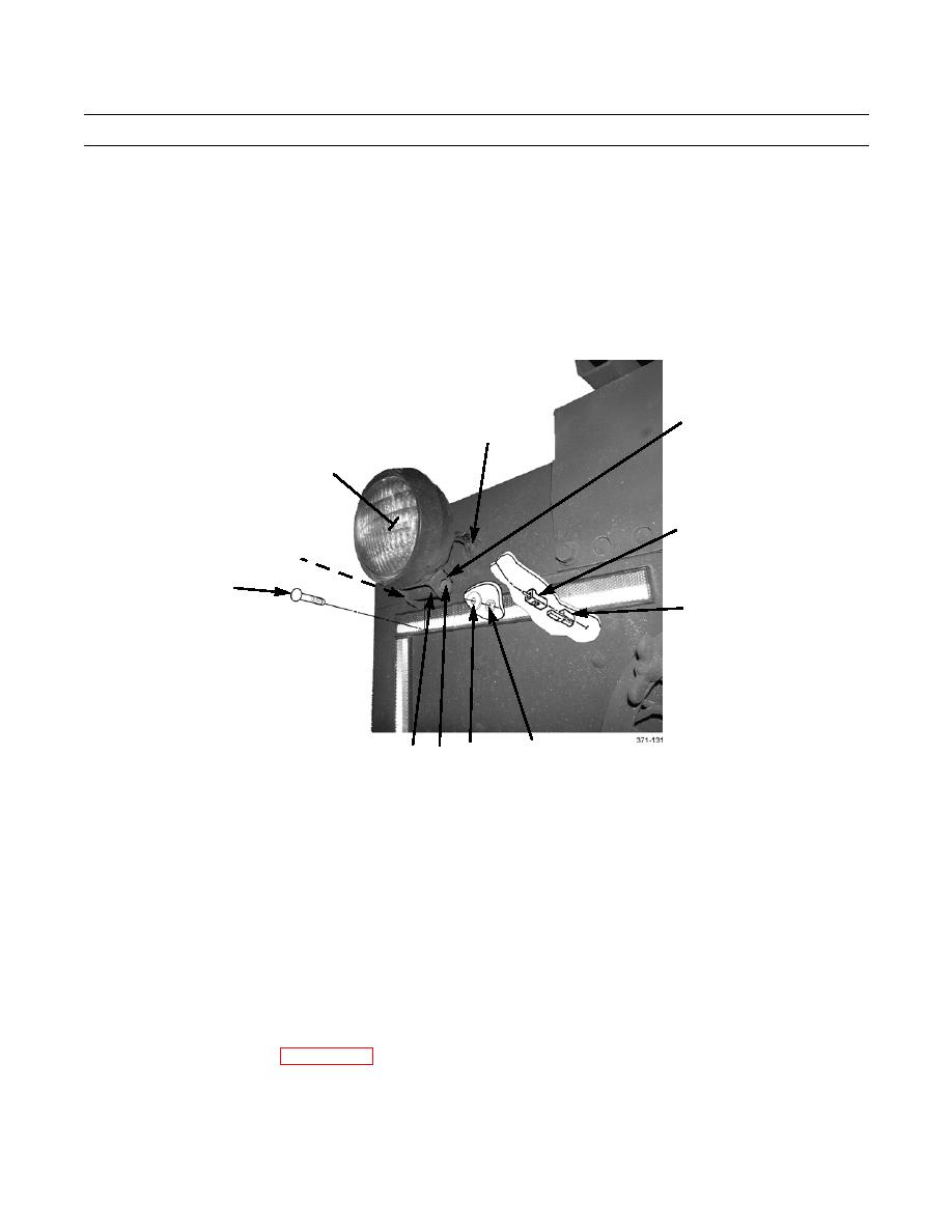
LIGHT ASSEMBLY REMOVAL
1.
Disconnect light assembly connector (8) from wiring harness connector (9).
2.
Remove grommet (6) and pull light assembly wiring out from inside cab.
3.
Remove locknut (15), bolt (12), spacer (13), and light assembly (4) from bracket (7). Discard locknut.
4.
If bracket (7) is damaged, remove nut (10), flatwasher (11), bolt (14), and bracket from rear of cab.
7
6
4
8
15
14
9
10
13 12 11
LIGHT ASSEMBLY INSTALLATION
1.
If bracket (7) was removed, install bracket to rear of cab with bolt (14), flatwasher (11), and nut (10).
2.
Feed light assembly connector (8) into cab.
3.
Connect light assembly connector (8) to wiring harness connector (9). Seat grommet (6).
4.
Position light assembly (4) on bracket (7) and install spacer (13), bolt (12), and new locknut (15).
5.
As required, adjust angle of utility light assembly (4) by loosening locknut (15), adjusting position of light, then tighten-
ing locknut.
6.
Apply caulk strip to provide weather tight seal for grommet (6) and wiring.
7.
Install cab and head liners (WP 0264 00) if removed.
END OF WORK PACKAGE
0109 00-2
|
|
Privacy Statement - Press Release - Copyright Information. - Contact Us |
