 |
|||
|
|
|||
|
|
|||
| ||||||||||
|
|
 TM 9-2320-302-20-2
CLEARANCE LIGHT REPLACEMENT (M915A3 NEW MODEL, M916A3, M917A2) - CONTINUED
0106 00
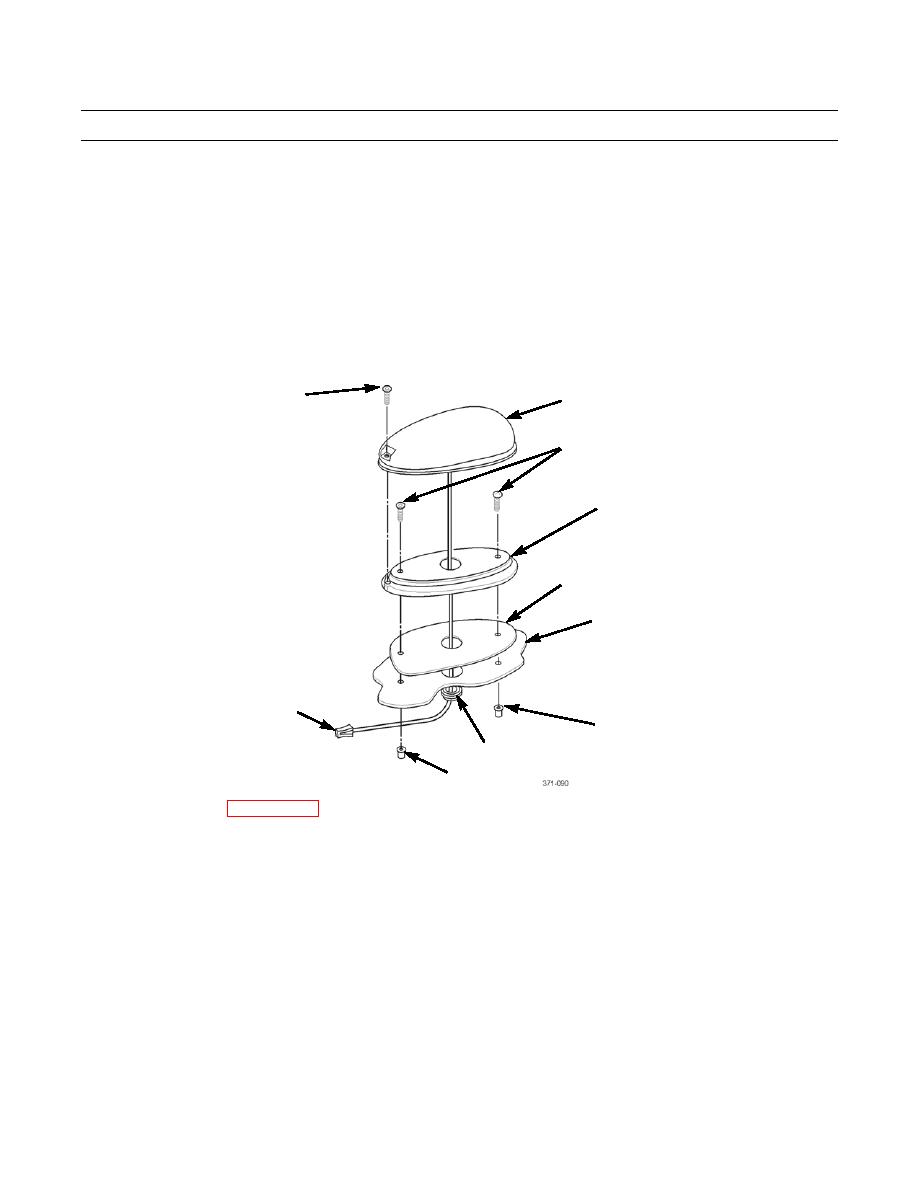
INSTALLATION
NOTE
Clearance light must be positioned with "FRONT" printed on base facing front of vehicle.
1.
Position grommet (8), gasket (5), and lens base (4) on cab roof (6) with clearance light connector (9) from lens assembly
(2) through opening in roof. Seat grommet in opening in roof.
2.
Install two screws (3) and threaded inserts (7).
3.
Connect wiring harness connector to clearance light connector (9).
4.
Position lens assembly (2) on lens base (4) and install screw (1).
1
2
3
4
5
6
9
7
8
7
5.
Install headliner(s) (WP 0264 00).
END OF WORK PACKAGE
0106 00-2
|
|
Privacy Statement - Press Release - Copyright Information. - Contact Us |
