 |
|||
|
|
|||
|
|
|||
| ||||||||||
|
|
 TM 9-2320-302-20-2
AIR COMPRESSOR GOVERNOR REPLACEMENT AND ADJUSTMENT - CONTINUED
0030 00
INSTALLATION
WARNING
Adhesives and sealing compounds can burn easily, can give off harmful vapors, and are harmful to skin
and clothing. To avoid injury or death, keep away from open fire and use in a well-ventilated area. If
adhesive or sealing compound contacts skin or clothing, wash immediately with soap and water.
Ensure that all air lines and fittings are free of debris and excess pipe sealing compound does not enter
air lines or fittings. Failure to follow this warning could result in injury to personnel and damage to
equipment.
1.
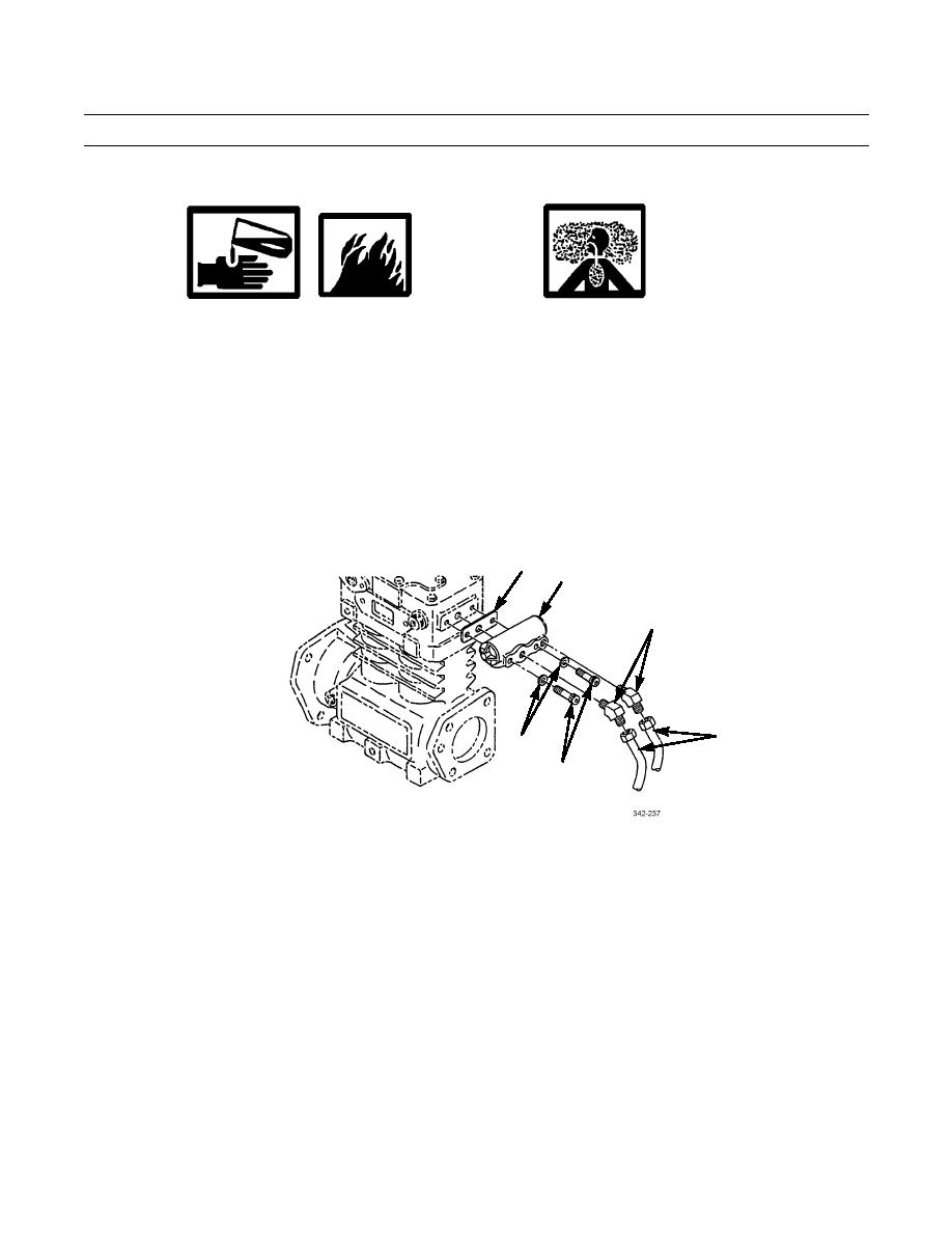
Lightly coat threads of two elbows (3) with pipe sealing compound. Install elbows in governor (2).
2.
Install new gasket (1) and governor (2) on compressor with two new lockwashers (6) and screws (5).
3.
Install two air lines (4) on elbows (3).
1
2
3
4
6
5
NOTE
Perform step 4 through 6 to verify correct operation of air compressor and governor.
4.
Start vehicle (TM 9-2320-302-10). Check for air leaks.
5.
Check air pressure gages when governor cuts out, stopping compression of air by compressor. Cut-out pressure should
be 120 psi (793 kPa) or 125 psi (862 kPa) for CTIS equipped vehicles.
6.
With engine running, make a series of brake applications to reduce air pressure. Observe air pressure gages when gover-
nor cuts in compressor. Cut-in pressure should be 95-100 psi (655-690 kPa).
NOTE
Air pressure operating range is 90-120 psi (621-827 kPa). If air pressure gages do not indicate within operat-
ing range, governor requires adjustment.
0030 00-2
|
|
Privacy Statement - Press Release - Copyright Information. - Contact Us |