 |
|||
|
|
|||
|
Page Title:
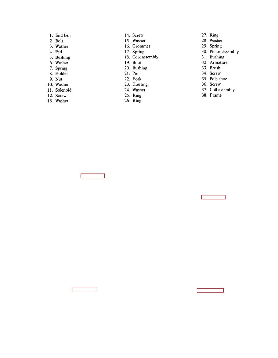
Figure 4-19. Starter (Sheet 2 of 2) |
|
||
| ||||||||||
|
|
 TM 55-1740-200-14
Figure 4-19. Starter (Sheet 2 of 2)
a. Remove four clamps (22) and remove two hoses (23
b. Carefully remove the instrument panel from the
and 24). Remove valve (21) from engine. Remove clamp
dashboard. Provide proper support while removing
(1) and hose (2).
terminal wires from the back of the instrument panel.
b. Disconnect leads from switch (16). Remove three
4-282. DISASSEMBLY. See figure 4-26 and dis-
nuts (6) and washers (7) and remove heater from tractor
assemble the instrument panel as follows:
cab.
a. Remove four connectors (9) and five lights (5) and
lead assemblies. Remove lamps from socket and lead
4-285. DISASSEMBLY. See figure 4-27 and dis-
assemblies.
assemble the cab heater as follows:
b. Remove six nuts (15), washers (16) and spacers
a. Remove four screws (5) and remove front panel (4).
(14). Remove cluster gage (17) and speedometer (18).
Slide the core assembly (8) and bottom panel (11) out of
Remove four screws (25), eight washers (26) and four
housing (20).
nuts (27). Remove circuit breakers (23 and 24).
b. Remove setscrew (10) and fan (9). Remove two
c. Unscrew three knobs and remove three retaining
nuts (13) and washers (14) and remove motor (12).
nuts. Remove wiper switch (20), floodlight switch (19)
Remove rubber grommet (15), rubber elbow (3) and plug
and headlight switch (22).
(17).
d. Pull off knob, remove nut and remove heater
c. Remove four rivets (19) and remove two doors (18)
switch. Remove the choke retaining nut from the back.
f r o m housing (20).
4-283. CAB HEATER.
4-286. FUEL SYSTEM.
4-284. REMOVAL. See figure 4-27 and remove the cab
4-287. REMOVAL. See figure 4-28 and remove the
fuel system as follows:
heater as follows:
a. Remove spring (38). Remove two nuts (33) and
washers (34) and remove connecting rod. Remove two
NOTE
ball joints (35) and nuts (36) from rod (37). Remove two
nuts (50) and washers (51) and remove connecting rod.
Provide proper receptacle and drain radiator
Remove two ball joints (52) and nuts (53) from rod (54).
coolant before removing heater.
4-55
|
|
Privacy Statement - Press Release - Copyright Information. - Contact Us |