|
| |
TM 5-2420-222-34
15-4.
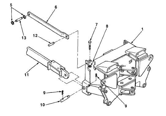
BACKHOE MAIN FRAME MAINTENANCE (Con’t).
4.
Remove two screws (7) and nuts (8) from main frame (1) and two pins (12).
5.
Drive two pins (12) out of main frame (1) and two towbars (6).
6.
Remove four cotter pins (9) from two pins (10) and side frames (11). Discard cotter pins.
7.
Drive two pins (10) out of main frame (1) and two side frames (11).
8.
Using lifting device and the aid of two assistants, lift main frame (1) off two towbars (6) and side frames (11) and
set on wood blocks.
9.
Remove lifting device from main frame (1).
10.
Using retaining ring pliers, remove four retaining rings (5) from two pins (13) and side frames (11).
b.
DISASSEMBLY
1.
Remove backhoe control valve-to-stabilizer cylinder oil lines (see TM 5-2420-222-20).
2.
Remove backhoe stabilizer cylinders (see TM 5-2420-222-20).
3.
Remove stabilizers (see TM 5-2420-222-20).
4.
Remove hydraulic impactor valve (see TM 5-2420-222-20).
5.
Remove swing cylinders (see TM 5-2420-222-20).
6.
If damaged, remove decal (see TM 5-2420-222-20).
TA701647
15-18
|