|
| |
TM5-2420-222-34
14-11
BACKHOE CROWD VALVE REPAIR (Con’t).
2.
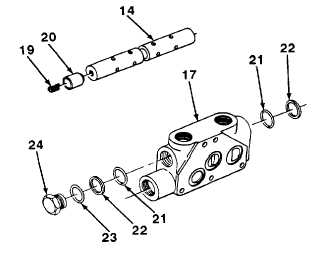
Install
preformed
packings
(21)
and
backup
washers (22) in valve body (17).
3.
Install relief valve In valve body (17) (see para-
graph 14-13).
4.
Coat new preformed packing (23) with hydraulic
fluid. Install plug (24) and preformed packing In
valve body (17).
5.
Install fluid flow restrictor (20) In place on spring
(19).
6.
Coat fluid flow restrictor (20) and spring (19) with
hydraulic fluid, then install in place on valve (14).
7.
Coat new preformed packing (15) with hydraulic
fluid and install in place on spool plug (16).
NOTE
Ensure that sealing surfaces are clean before applying thread sealing compound to
spool plug.
8.
Apply thread sealing compound to threads of spool plug (16).
9.
Wrap valve (14) with a clean rag and place in vise with caps. Install spool plug (16) and preformed packing (15) in
valve.
NOTE
Ensure that sealing surfaces are clean before applying thread sealing compound to
clevis rod end.
10.
Coat new preformed packing (13) with hydraulic fluid and install in place on clevis rod end (12).
11.
Apply thread sealing compound to threads of clevis rod end (12). Install clevis rod end and assembled parts on
valve (14). Remove valve from vise.
12.
Coat two new preformed packings (7 and 18) and sleeve bushing (6) with hydraulic fluid. Install sleeve bushing
and preformed packings in valve body (17).
13.
Coat valve (14) with hydraulic fluid and slide into valve body (17).
14.
Install spring pin (5) and two washers (3) in valve body (17).
15.
Coat spool spring (4) with hydraulic fluid and install in valve body (17).
16.
Hold clevis rod end (12) to prevent turning, and install bolt (2) in spool plug (16). Torque bolt to 5-8 lb.-ft. (7-10
N•m)
17.
Place valve body (17) in vise with caps. Install valve cap (1) in valve body. Remove valve body from vise.
18.
Install washer (11), bellows (10), and protective dust cap (9) over clevis rod end (12) and secure with two
capscrews (8).
FOLLOW-ON TASKS:
•
Assemble backhoe control valve assembly (see paragraph 14-9).
TA701589
14-59
|

