|
| |
TM 5-2420-222-34
14-3.
HYDRAULIC PUMP ASSEMBLY MAINTENANCE (Con’t).
NOTE
Shims are available in two sizes; 0.006 in. (0.152 mm) and 0.010 in. (0.254 mm).
Add or remove shim(s) until end play specification Is met.
19.
If measurement in step 17 was less than 0.001 in. (0.025 mm) add shim(s) (35) as required. If measurement was
more than 0.003 in. (0.076 mm) remove shim(s) as required.
20.
Repeat steps 16 through 19 until end play measurement in step 17 is 0.001-0.003 in. (0.025-0.076 mm).
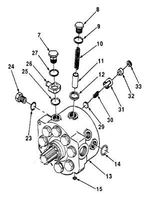
21.
Install eight outlet valves (29), springs (30), guides (31), valve
stops (32), and new discharge packings (33) in hydraulic
pump housing (13).
NOTE
To ensure proper Installation of pistons, springs,
and plugs, turn shaft until piston being installed
Is on the low part of shaft.
22.
Apply thin coat of hydraulic fluid to eight pistons (11) and
springs (10). Install piston and springs in hydraulic pump
housing (13).
23.
Install eight sheaths (12), new preformed packings (9), and
plugs (8). Torque plugs to 100 lb.-ft. (136 N•m).
24.
Install new preformed packing (25) on elbow (26) and install
elbow in hydraulic pump housing (13).
25.
Install new preformed packing (27) on plug (7) and install plug
in hydraulic pump housing (13).
26.
Install new preformed packing (23) on plug (24) and install
plug in hydraulic pump housing (13).
27.
Install new preformed packings (14 and 15) in hydraulic pump
housing (13).
e.
INSTALLATION
1.
Install shim(s) (35) and stroke control valve (4) on hydraulic pump housing (13) with match-marks alined.
2.
Install four screws (6). Torque screws to 85 lb.-ft. (115 N•m).
TA701 556
14-21
|