|
| |
TM 5-2420-222-34
10-1.
PARKING BRAKE BAND AND LINING MAINTENANCE (Con’t).
d.
ASSEMBLY
NOTE
Perform steps 1 and 2
only if linings were
removed.
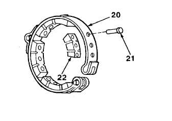
1.
Position four linings (22) and 12 rivets (21) in
place on brake band (20).
2.
Using brake and clutch reliner, peen ends of
rivets (21) over to secure linings (22).
e.
INSTALLATION
1.
Spread ends of brake band and lining (1) and rotate into position on parking brake drum (17) and anchor band
(11).
2.
Install spring (2) on grooved pin (4) and spring pin (3) in shouldered pin (12).
3.
Install straight pin (10) and washer (13) in anchor band (11) and brake band and lining (1). Install new cotter pin
(19) in straight pin.
4.
Install special capscrew (8) partway In brake band and lining (1) and shouldered pin (12).
5.
Install special screw (16) partway In transmission (9). Install new preformed packing (15) in place on special screw
and transmission.
6.
Install nut (14) partway on special screw (16).
7.
Install elbow (5) and adapter (7) in transmission (9). Connect auger bleed line (6) to elbow.
8.
Set and release parking brake lever five times to seat linkage (see TM 5-2420-222-10).
9.
Adjust parking brake (see TM 5-2420-222-20).
10.
Set parking brake lever (see TM 5-2420-222-10).
11.
Install transmission top cover (see paragraph 8-12 or 8-13).
12.
Fill transmission (see LO 5-2420-222-12).
NOTE
Steps 13 through 21 apply only if new linings were Installed.
13.
Ensure that front wheels are straight ahead. Block front wheels.
14.
Using hydraulic floor jack, raise left side rear axle housing (18) until tire is off ground, then support with jackstand
and remove hydraulic floor jack.
10-4
|