|
| |
TM 5-2420-222-34
8-7.
DIFFERENTIAL ASSEMBLY MAINTENANCE (Con’t).
9.
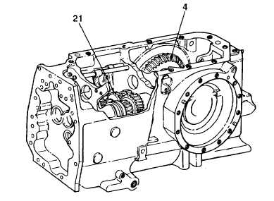
Using dial indicator, turn differential drive shaft (21) back and forth and note backlash. Backlash with new parts
must be 0.006-0.008 in. (0.152-0.203 mm). Backlash with used parts must not exceed 0.0, 2 in. (0.305 mm) at
point of greatest backlash.
NOTE
If backlash in step 9 is as specified, skip steps 10 through 12.
10.
Remove ten bolts (1) from left and right differential quills (2 and 6) and transmission (5).
11.
Using lifting device, support differential gear assembly (4) and remove left and right differential quills (2 and 6)
from differential gear assembly and transmission (5).
NOTE
Do not add or subtract number of shims being used. Subtracting or adding shims
to obtain proper backlash will change differential bearing preload adjustment.
12.
If backlash noted in step 9 was more than specified, move one shim (3) from left to right side. If backlash was
less than specified, move one shim from right to left side. Install ten bolts (1) in left and right differential quills (2
and 6) and transmission (5). Torque bolts to 35 lb.-ft. (47 Nom).
13.
Disconnect lifting device from differential gear assembly (4).
14.
Apply light coat of Prussian blue dye to contact surfaces of gear teeth of differential gear assembly (4) and
differential drive shaft (21).
15.
Turn differential drive shaft (21) one full revolution. Using vernier caliper, measure distance between bevel gear
end of differential drive shaft and start of tooth pattern.
16.
Distance from bevel gear end of differential drive shaft (21) and start of tooth pattern must be 0.120-0.360 in.
(3.048-9.144 mm). If distance is not as specified, repeat steps 9 through 16 to determine cause.
TA701381
8-40
|