|
| |
TM 5-2420-222-34
4-1.
CLUTCH ASSEMBLY MAINTENANCE (SERIAL NUMBERS 235786-235999) (Con’t).
3.
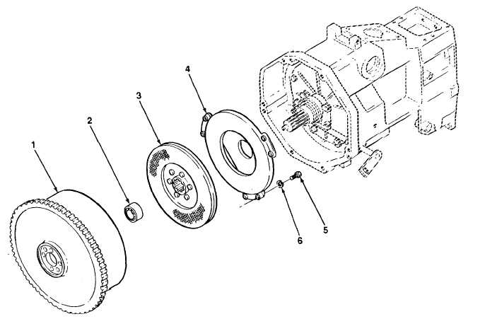
Install pilot ball bearing (2) in flywheel (1).
4.
Position clutch alining tool in place on pilot ball bearing (2). Install clutch disk (3) on clutch alining tool and against
flywheel driving surface. Ensure that long end of clutch disk faces away from flywheel (1).
5.
Install clutch disk assembly (4) on clutch alining tool, clutch disk (3), and flywheel (1), then aline match-marks.
6.
Install six screws (5) and new lockwashers (6) one at a time, until spring tension is felt. Tighten each screw one turn,
then repeat until all six screws are tight.
7.
Torque six screws (5) to 25 lb.-ft. (34 N•m). Remove clutch alining tool.
f.
ADJUSTMENT
1.
Working on one remote control lever (16) at a time, loosen jamnut (21) and lever screw (18) on pressure plate (14)
and clutch disk assembly (4). Position step of clutch finger alining tool over remote control lever.
2.
Loosen or tighten lever screw (18) until legs of clutch finger alining tool rest evenly on flywheel (1), then tighten jamnut
(21).
TA701309
4-8
|

