|
| |
TM 5-2420-222-34
1-16.
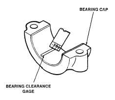
BEARING CLEARANCE GAGE (Con’t]
(4)
Remove bearing shell and cap. Flattened gage will remain
stuck to either bearing shell or crankshaft.
(5)
Compare width of flattened gage at its widest point with
graduations on envelope. Number within graduation on envelope indicates
bearing clearance in thousandths of an inch.
(6)
Taper may be indicated when one end of flattened gage is
wider than the other. Measure each end of gage; the difference between
readings is the a proximate amount of taper.
1-17.
SERVICE REPLACEMENT KITS.
Many service replacement parts are available In various undersize and/or oversize, as well as standard sizes.
Service kits for reconditioning certain parts and service sets which include all parts necessary to complete task are also
available.
1-18.
TAGGING PARTS.
a.
Use marker tags (Item 32, Appendix B) to identify all electrical wires, hydraulic, fuel, oil, and coolant lines, and
any other parts which may be hard to identify or replace later. Fasten tags to parts during removal by wrapping wire
fasteners around or through parts and twisting ends together. Position tags to be out of the way during cleaning,
inspection, and repair. Mark tags with a pencil, pen, or marker.
b.
Whenever possible, identify electrical wires with number of terminal or wire to which it connects. If no
markings can be found, tag both wires or wire and terminal, and use same identifying mark for both. If you cannot tag wire
because it must fit through small hole or you cannot reach it, write down description of wire and the point to which it
connects or draw a simple diagram on paper. Be sure to write down enough information so you will be able to connect
wires properly during assembly. If you need to identify loose wire, look for identifying numbers near end of wire, stamped
on a permanent metal tag. Compare this number to wire numbers on appropriate electrical schematic in TM 5-2420-222-
20.
c.
Identify hydraulic, fuel, oil, and coolant lines whenever you are taking off more than one line at the same time.
Mark tags with points to which lines and hoses must be connected. For example: "Bulkhead adapter to scarifler cylinder
tube and adapter" might be written on tag for hydraulic hose. If it is not obvious which end of a line goes where, tag each
end of line.
d.
Identify and tag other parts as required by name and installed location.
TA701214
1-8
|

