|
| |
TM 5-2420-222-34
3-19. CONTROL CAMS, GEARS, AND BUSHINGS REPLACEMENT (Con’t).
4.
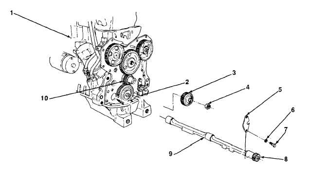
Lubricate control cam journals with engine oil. Slide control cam (9) with assembled parts into engine block (1).
5.
Position thrust plate (5) in place on engine block (1). Install two screws (7) and new lockwashers (6) in thrust plate
and engine block. Torque screws to 35 lb.-ft. (47 N•m).
6.
Rotate control cam spur gear (8) until timing slash-mark is alined with center of crankshaft (10). Using timing
alinement tool, ensure that timing slash-mark is alined with center of crankshaft.
NOTE
Perform steps 7 and 8 only if left control cam was removed.
7.
Position engine oil pump spur gear (3) in place on engine oil pump drive shaft (2) with timing slash-mark alined
with center of crankshaft (10). Using timing alinement tool, ensure that timing slash-mark is alined with center of
crankshaft.
8.
Install new jamnut (4) on engine oil pump drive shaft (2) and engine oil pump spur gear (3). Torque jamnut to 35-
45LB.-FT. (47-61 N•m). Stake jamnut to drive shaft.
FOLLOW-ON TASKS:
•
Install lower idler spur gear (see paragraph 3-15).
•
Time engine (see paragraph 3-16).
•
Install engine oil pan (see paragraph 3-20).
TA701296
3-114
|