|
| |
TM 5-2420-222-20-3
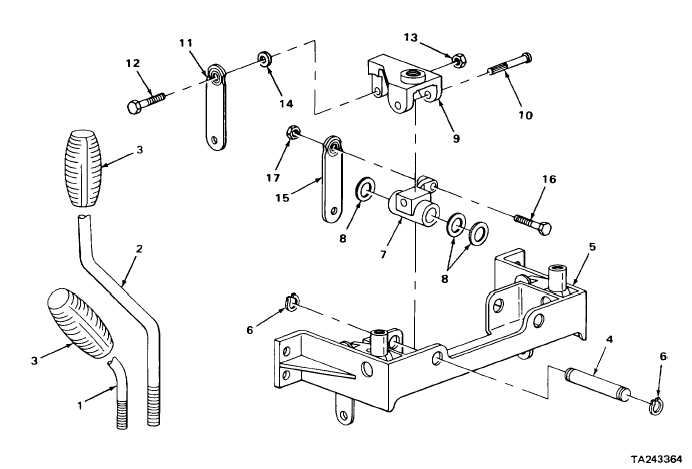
BACKHOE CONTROL VALVE LEVERS AND LINKAGE (SERIAL NUMBERS 319995 THRU 342573 ONLY) -
CONTINUED
ACTION
LOCATION
ITEM
REMARKS
15.
Pivot link (7)
Screw (16) and
a.
Using 1/2-inch, 1/2-inch drive socket,
and connector
special nut (17)
ratchet handle, and 1/2-inch box
link (15)
wrench, unscrew and take apart.
b.
Get rid of special nut (17).
16.
Pivot link(9)
Connector link (15)
a.
Take off.
b.
Repeat steps 8 thru 16 for backhoe
boom control lever linkage.
NOTE
Linkage for both stabilizer control levers is disassembled the same way. Left
stabilizer control lever linkage is shown. Repeat steps 17 thru 21 for right stabilizer
control lever linkage.
2-1317
|