 |
|||
|
|
|||
|
|
|||
| ||||||||||
|
|
 TM 5-2410-237-23
BLADE CONTROL VALVE (LIFT AND TILT) REPAIR - CONTINUED
0245 21
ASSEMBLY - CONTINUED
CAUTION
Ensure all O-rings and seals are seated properly when assembling cover to valve body. Cut or pinched O-
rings and seals could cause leaks and system malfunctions.
48.
Carefully position cover (6) on valve body (14) and install four bolts (12) and washers (13).
NOTE
Shims are added or removed, as needed, to adjust main pressure relief valve setting (WP 0167 00).
Adding one shim increases pressure by 35 psi (241 kPa). Removing one shim decreases pressure by the
same value.
Unless hydraulic system pressure test results (WP 0167 00) have indicated the need to add or remove
shims, the same number of shims should be installed as were removed.
49.
Install two relief pilot valves (11), new springs (10), pistons (9) and shims (8) in cover (6).
NOTE
Two plugs are marked with pressure settings for respective pressure relief valve and must be installed per
marking. Plug for bulldozer blade lift and ripper lift is stamped "15 500 kPa." Plug for blade tilt is stamped
"16 900 kPa."
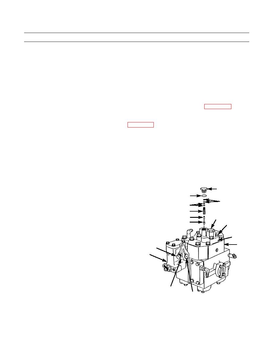
50.
Install new O-ring (7) on each of two plugs (5) and
5
install plugs in cover (6). Tighten plugs to 80 lb-ft
7
(108 Nm).
8
8
51.
Install key (3) and lever (2) on shaft (4) at control
lever housing (63) and tighten bolt (1) to secure lever.
10
5,7
9
52.
Install protective caps in blade control valve.
11
12,13
6
14
1
63
2,3
4
421-0061
END OF WORK PACKAGE
Change 1
0245 21-14
|
|
Privacy Statement - Press Release - Copyright Information. - Contact Us |
