 |
|||
|
|
|||
|
|
|||
| ||||||||||
|
|
 TM 5-2410-237-23
WINCH CONTROL VALVE REPAIR - CONTINUED
0245 20
ASSEMBLY - CONTINUED
NOTE
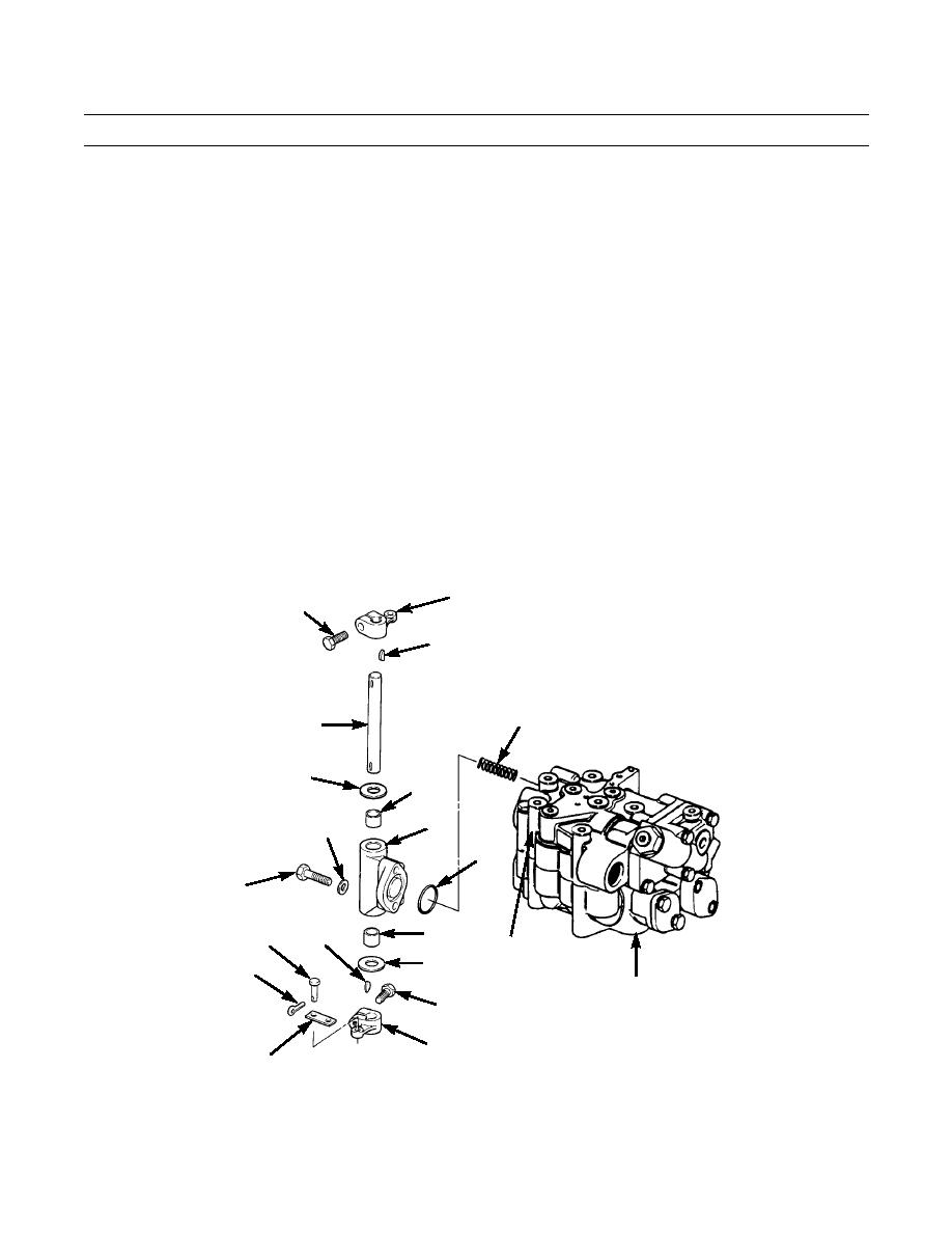
Bushings must be installed 0.06 in. (1.5 mm) below end surfaces of bracket.
38.
Install two new bushings (19) in bracket (8).
39.
Install new washer (18) on shaft (6).
40.
Install new key (17) on shaft (6).
41.
Slide lever (16) on shaft (6). Tighten capscrew (15) on lever.
42.
Install spring (13) into valve assembly (12). Install new preformed packing (14) on bracket (8).
43.
Install bracket (8) on valve body (12). Install two new lockwashers (11) and capscrews (10).
44.
Install shaft assembly (6) on bracket (8).
45.
Install new washer (9) on shaft (6).
46.
Install new key (7) on shaft (6).
47.
Slide lever (5) on shaft (6). Tighten capscrew (4) on lever.
48.
Install two links (3) on valve spool (38) and lever (16). Install two straight head pins (2) and new cotter pins (1) to
secure links.
5
4
7
13
6
9
19
8
11
14
10
19
17
2
38 (HIDDEN)
18
1
12
15
421-0180
16
3
END OF WORK PACKAGE
Change 1
0245 20-14
|
|
Privacy Statement - Press Release - Copyright Information. - Contact Us |