 |
|||
|
|
|||
|
|
|||
| ||||||||||
|
|
 TM 5-2410-237-23
WINCH ASSEMBLY REPAIR - CONTINUED
0245 19
ASSEMBLY - CONTINUED
NOTE
Bevel gears must be aligned before pinion assembly can be installed in winch. If bevel gears are not aligned,
correct pinion adjustments will not be possible.
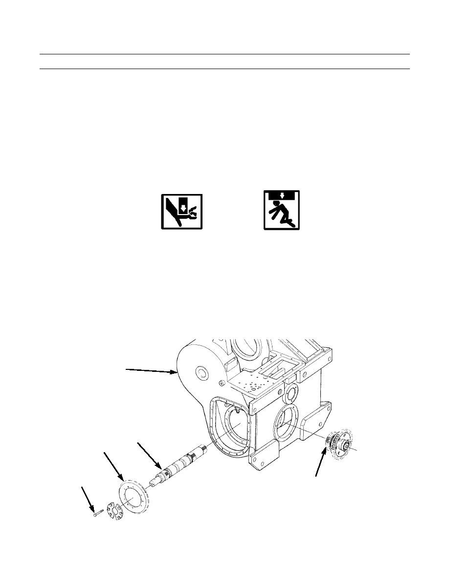
am. Position pinion assembly (assembled in Assembly step 1) so that pinion gear (127) is between two bevel gears
(200).
an. Push pinion gear (127) as far as it will go to ensure bevel gears (200) are aligned.
ao. Tighten capscrews (178) to 36 lb-ft (49 Nm).
WARNING
Use extreme caution when handling heavy parts. Provide adequate support and use assistance during pro-
cedure. Ensure that any lifting device used is in good condition and of suitable load capacity. Keep clear of
heavy parts supported only by lifting device. Failure to follow this warning may result in injury or death.
NOTE
Clutch shaft with assembled clutch assemblies weighs 350 lb (159 kg).
ap. Fasten lifting equipment and position clutch shaft with assembled clutch assemblies part way into case (5).
aq. Support clutch shaft (155) and reconnect lifting equipment from inside case (5). Move clutch shaft with assembled
clutch assemblies all the way into case.
5
155
200
127
178
421-0316
Change 1
0245 19-26
|
|
Privacy Statement - Press Release - Copyright Information. - Contact Us |
