 |
|||
|
|
|||
|
|
|||
| ||||||||||
|
|
 TM 5-2410-237-23
TRANSMISSION ASSEMBLY REPAIR - CONTINUED
0245 15
DISASSEMBLY - CONTINUED
102. Bend six locks (166) down.
103. Remove 11 capscrews (167) and locks (166) from cover (156). Discard locks.
104. Install three 3/8-16NC forcing screws in threaded
bores (168). Tighten forcing screws evenly until cover
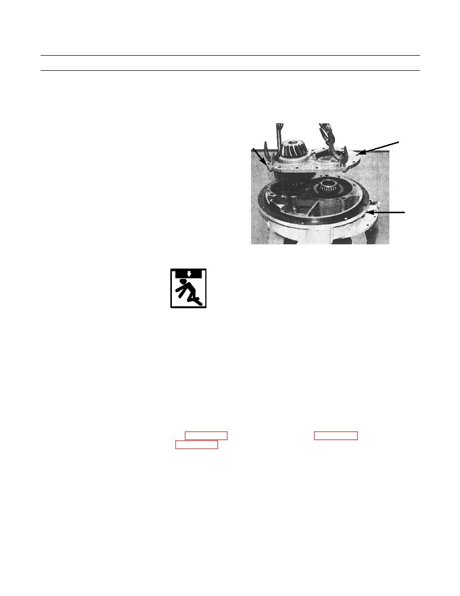
LIFTING
(156) assembly is free from transfer gear case (19).
156
LINKS
19
421-0263
WARNING
Use extreme caution when handling heavy parts. Provide adequate support and use assistance during pro-
cedure. Ensure that any lifting device used is in good condition and of suitable load capacity. Keep clear of
heavy parts supported only by lifting device. Failure to follow this warning may result in injury or death.
NOTE
Weight of case assembly is 80 lb (36 kg).
105. Remove forcing screws and install three lifting links in threaded bores (168) with 3/8-16NC bolts, attach lifting device
and remove cover (156) assembly from transfer gear case (19).
106. Remove gear (169) from transfer gear case (19).
107. Remove capscrew (170) and washer (171) from pinion (172).
108. Use press to remove race and roller assembly (173), gear (174) and cover (156) from pinion (172).
109. Use mechanical puller attachment (Item 81, WP 0250 00), mechanical puller (Item 89, WP 0250 00), ratchet wrench and
mechanical puller step plate (Item 180, WP 0250 00) to remove race and roller assembly (175) from pinion (172).
Change 1
0245 15-18
|
|
Privacy Statement - Press Release - Copyright Information. - Contact Us |
