 |
|||
|
|
|||
|
|
|||
| ||||||||||
|
|
 TM 5-2410-237-23
ELECTRICAL GENERAL MAINTENANCE INSTRUCTIONS - CONTINUED
0242 00
SPLICING WIRES
NOTE
The selection of crimping tool and type of splice connectors is optional.
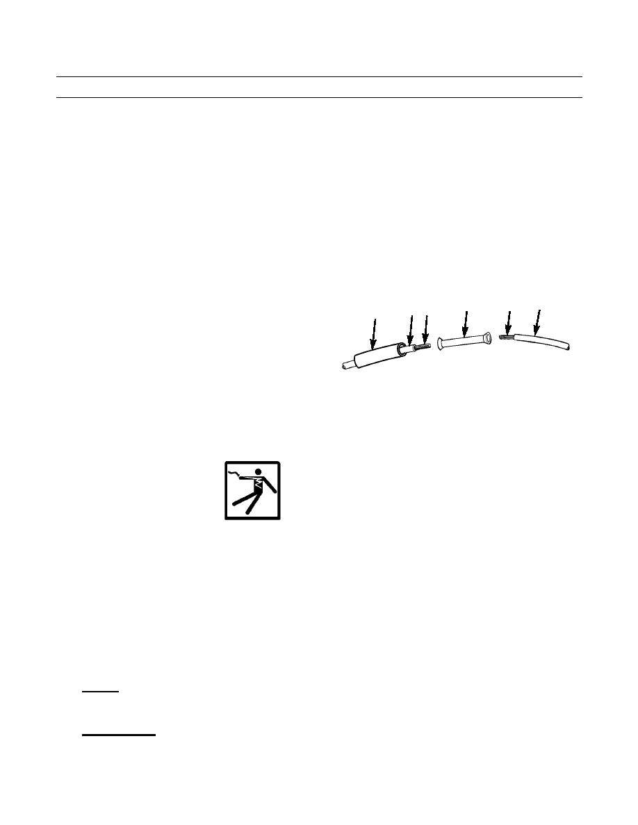
1.
Inspect each end of wire (25). Trim insulation and metal strands (26) of wire back, as necessary, to ensure integrity of
wire.
2.
Strip each end of wire (25) to expose length of metal strands (26) to suit type of splice connector (27) used.
NOTE
Perform steps 3 and 4 at each end of splice connector.
3.
Insert metal strands (26) of wire (25) fully into splice connector (27).
4.
Cut length of insulation sleeving (28) at least 3/4 in.
26
27
25
25 26
28
(19 mm) longer than length of splice connector (27)
and slide insulation sleeving over one wire (25).
5.
Securely crimp splice connector (27) to metal strands
(26) of wire (25).
6.
Center insulation sleeving (28) over splice connector
387-798
(27) and use heat gun to shrink insulation sleeving.
ELECTRICAL GROUND POINTS
Many electrical problems are the result of poor ground connections. Ensure that ground connections are good by per-
forming the following steps:
WARNING
Although battery disconnect switch must be ON to test electrical circuit voltage, turn battery disconnect
switch to OFF before performing resistance tests or replacing parts. Failure to follow this warning may
result in injury to personnel and damage to parts or equipment.
a.
Remove screw, lockwasher, nut, etc. connecting ground wire terminal to machine ground point.
b.
If necessary, clean mounting hardware, wire terminal, and ground point with detergent and a scrub brush.
c.
Remove any rust or corrosion from ground point with a wire brush and abrasive cloth.
d.
Replace defective mounting hardware and wire terminal as necessary.
e.
Install wire terminal to ground point with screw, lockwasher, nut, etc. and tighten securely.
MULTIMETER USAGE
1.
General. A multimeter is used to troubleshoot the electrical system of the machine. The multimeter ohms scale is used
to test for continuity, shorts and resistance. The multimeter voltmeter scale is used to test voltage levels in the electrical
system.
2.
Continuity Tests. Continuity tests are performed to check for breaks in a circuit (such as a fuse, switch, light bulb con-
nector or electrical wiring).
0242 00-4
|
|
Privacy Statement - Press Release - Copyright Information. - Contact Us |
