 |
|||
|
|
|||
|
Page Title:
A/C UNIT INSTALLATION - CONTINUED |
|
||
| ||||||||||
|
|
 TM 5-2410-237-23
AIR CONDITIONING INSTALLATION INSTRUCTIONS - CONTINUED
0229 03
A/C UNIT INSTALLATION - CONTINUED
NOTE
For more information, refer to wiring diagram at the end of this work package.
19.
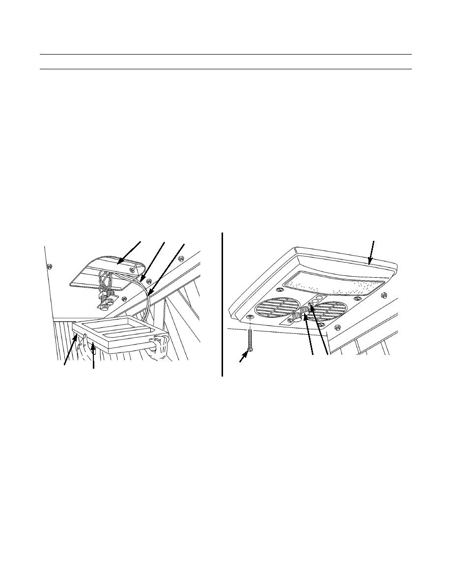
From inside of cab, route red wire (22) and white wire (23) through 3/4 in. slot on left side of A/C unit (7), making sure
wires are not pinched.
20.
Remove cutouts from foam gasket (24) and place gasket in plastic plenum assembly (25).
21.
Raise plenum assembly (25) and gasket (24) to A/C unit (7) and start one 10-32 x 3 in. screw (26).
22.
Attach switch panel (27) to plenum (25) with two 10-32 x 1/2 in. screws (28).
23.
Continue mounting plenum (25) with three remaining 10-32 x 3 in. screws (26).
NOTE
For more information, refer to wiring diagram at the end of this work package.
24.
Tighten all four screws (26) evenly until plenum (25) fits snugly against roof interior. Make sure wires (22 and 23) are
routed without pinching.
25
7
22
23
28
27
421-0331
26
421-0330
25
24
25.
Disassemble 4R9709 harness assembly (29) and feed wires (22 and 23) provided with A/C unit (red 10 ft and white
20 ft) through harness assembly.
26.
Remove dash cover (30) and feed red wire (31) of 4R9939 harness assembly from inside of dash through hole in side of
dash (32).
27.
Insert fuse (34) in 4R9939 harness assembly (33) if not already done.
28.
Butt-splice red wire (31) of 4R9939 harness assembly (33) with red wire (22) routed through 4R9709 harness assembly
(29).
Change 1
0229 03-6
|
|
Privacy Statement - Press Release - Copyright Information. - Contact Us |