 |
|||
|
|
|||
|
|
|||
| ||||||||||
|
|
 TM 5-2410-237-23
INSTALLATION OF ARMOR PACKAGE - CONTINUED
0228 00
INSTALLATION - CONTINUED
(11)
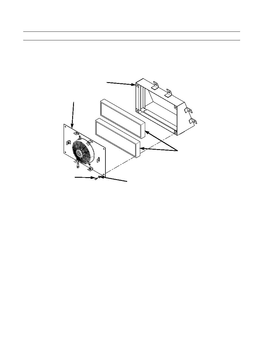
Install two filters (327) in case assembly (315).
(12)
Install mounting plate (311) with fan (307) on case assembly (315) with four bolts (328) and washers
(329). Tighten bolts to 35 lb-ft. (47 Nm).
315
311
327
328
329
387-987
(13)
Place shroud (319) close enough to case assembly (315) to make harness connections.
(14)
Connect fan harness (306) resistor connectors to upper and lower resistor (322) connectors blades.
(15)
Route fan harness (306) power lead and ground lead through center hole in top of shroud (319).
(16)
Route fan harness (306) ON/OFF switch (330) through hole in front of shroud (319). Adjust position and
secure switch with jam nuts and lockwashers provided with switch.
(17)
Attach shroud (319) to case assembly (315) with six bolts (331) and washers (332). Attach fan harness
(306) ground lead to mounting bolt located at top left of case assembly.
(18)
Tighten bolts (331) to 35 lb-ft. (47 Nm).
(19)
Install grommet (333) on fan harness (306) at top of shroud (319).
(20)
Install six louvers (334) in shroud (319) with four screws (335) each louver.
0228 00-34
|
|
Privacy Statement - Press Release - Copyright Information. - Contact Us |