 |
|||
|
|
|||
|
|
|||
| ||||||||||
|
|
 TM 5-2410-237-23
BLADE HYDRAULIC LINES AND FITTINGS REPLACEMENT - CONTINUED
0213 00
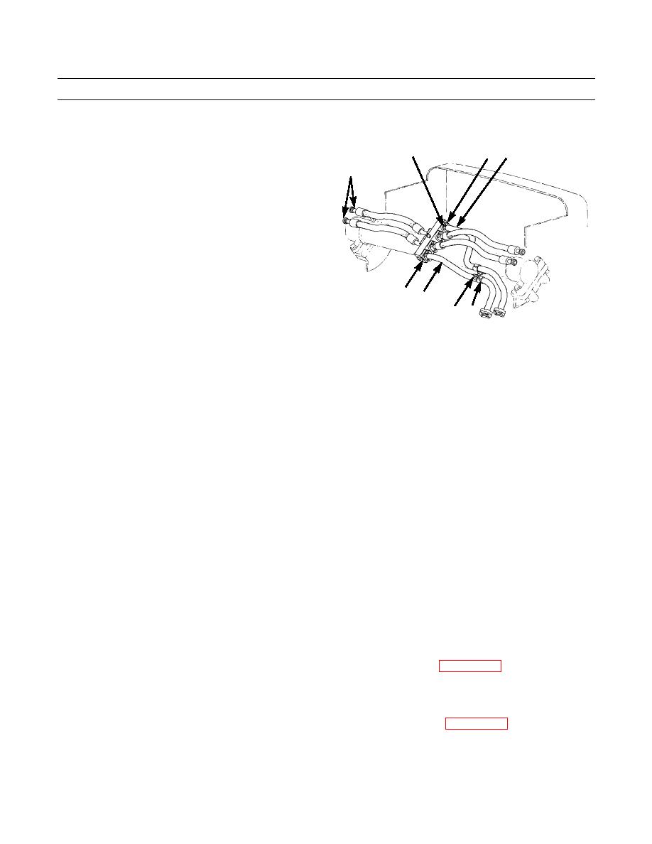
REMOVAL - CONTINUED
3.
Remove four capscrews (10), washers (11), two split
12,13
10,11 14
TO L.H. BLADE
flanges or regular flange (12), O-ring (13) and hydrau-
LIFT CYLINDER
lic hose (14) from manifold (15) above lift cylinder
mounting tube. Discard O-ring.
4.
Remove capscrew (16), lockwasher (17), washer (18)
and retaining strap (19) from hydraulic hose (14). Dis-
card lockwasher.
15 14
16,17,18 19
387-727
INSTALLATION
CAUTION
Wipe all sealing surfaces and hose connections clean and dry prior to installation. Contamination of
hydraulic system could result in premature failure.
Utilize line wrenches for installation to avoid damage to fittings and connectors.
NOTE
Lightly coat new O-rings with clean oil before installation.
Mounting hardware for retaining straps may vary depending on type and location of strap.
1.
Secure hydraulic hose (14) with retaining strap (19), washer (18), new lockwasher (17) and capscrew (16).
2.
Install end of hydraulic hose (14) on manifold (15) with new O-ring (13), two split flanges or regular flange (12), four
washers (11) and capscrews (10).
3.
For hydraulic hoses held in position with retaining straps, install retaining strap (9) on hydraulic hose or hoses with cap-
screw (6), washer (7) and new lockwasher (8).
4.
Install end of hydraulic hose (4) with new O-ring (5), two split flanges or regular flange (3), four washers (2) and cap-
screws (1).
5.
Check oil level in hydraulic tank. Refill tank and bleed air from system, as required (WP 0225 00).
6.
Cycle cylinders and check for proper operation and leaks. Stop engine and reposition fittings if hydraulic hoses pull
tight.
7.
Ensure that oil level is still visible in sight gage on hydraulic tank. Add oil as needed (WP 0225 00).
END OF WORK PACKAGE
0213 00-3
|
|
Privacy Statement - Press Release - Copyright Information. - Contact Us |
