 |
|||
|
|
|||
|
|
|||
| ||||||||||
|
|
 TM 5-2410-237-23
BLADE CONTROL LEVER AND LINKAGE REPLACEMENT - CONTINUED
0207 00
INSTALLATION - CONTINUED
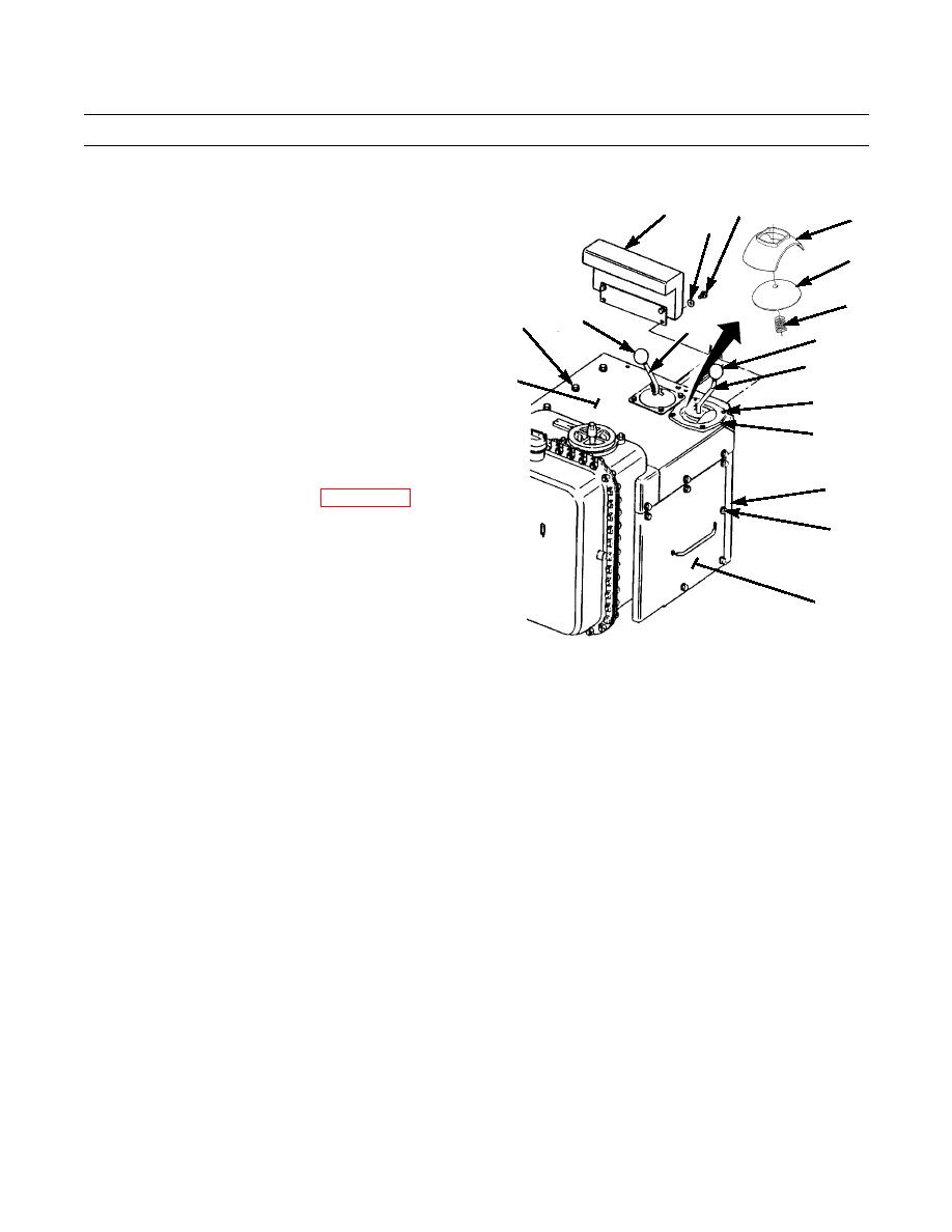
21.
Place spring (19), dome (18) and guide (17) on blade
1
3
17
control lever (6).
2
22.
Install plate (16) to control console (4) with six wash-
18
ers (15) and capscrews (14).
23.
Install cover (11) to control console (4) with nine
19
washers (13) and capscrews (12).
12,13
7
8
24.
Place cover (10) over blade control lever (6). Position
5
guide (17) in cover and install cover to cover (11) with
6
four screws (9).
11
25.
Install knob (5) on blade control lever (6) and knob (7)
9
on ripper or winch control lever (8) (whichever
applies).
10
26.
Install armrest (3) to control console (4) with two
washers (2) and capscrews (1).
4
27.
Install steering brake lock lever (WP 0149 00).
14,15
16
387-641
28.
Operate machine and check blade control lever for proper operation (TM 5-2410-237-10).
END OF WORK PACKAGE
0207 00-10
|
|
Privacy Statement - Press Release - Copyright Information. - Contact Us |