 |
|||
|
|
|||
|
|
|||
| ||||||||||
|
|
 TM 5-2410-237-23
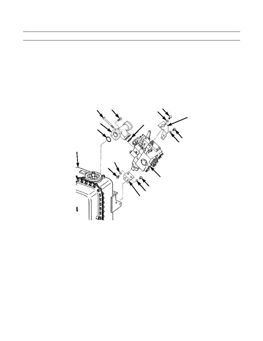
BLADE CONTROL VALVE (LIFT AND TILT) REPLACEMENT - CONTINUED
0201 00
REMOVAL - CONTINUED
7.
Remove two capscrews (19), washers (20) and upper bracket (15) from blade control valve (1).
8.
Remove two capscrews (21), washers (22) and lower bracket (18) from blade control valve (1).
9.
Remove O-ring (23) from manifold (12) and discard O-ring.
10.
Remove two capscrews (24), manifold (12) and O-ring (25) from blade control valve (1). Discard O-ring.
INSTALLATION
19
11
24
20
15
12
25
23
13
14
2
22
21
1
16
17
18
387-589
CAUTION
Wipe all connectors and sealing surfaces on hydraulic tank and control valve clean and dry before installation, to pre-
vent contamination from entering hydraulic system.
NOTE
Lightly coat new O-rings with clean oil before installation.
Apply sealing compound to pipe threads.
1.
Install new O-ring (25) and manifold (12) to blade control valve (1) with two capscrews (24).
2.
Install new O-ring (23) in manifold (12).
3.
Install lower bracket (18) to blade control valve (1) with two capscrews (21) and washers (22).
4.
Install upper bracket (15) to blade control valve (1) with two capscrews (19) and washers (20).
0201 00-3
|
|
Privacy Statement - Press Release - Copyright Information. - Contact Us |
