 |
|||
|
|
|||
|
|
|||
| ||||||||||
|
|
 TM 5-2410-237-23
WINCH CONTROL LEVER AND LINKAGE REPLACEMENT - CONTINUED
0183 00
REMOVAL - CONTINUED
17.
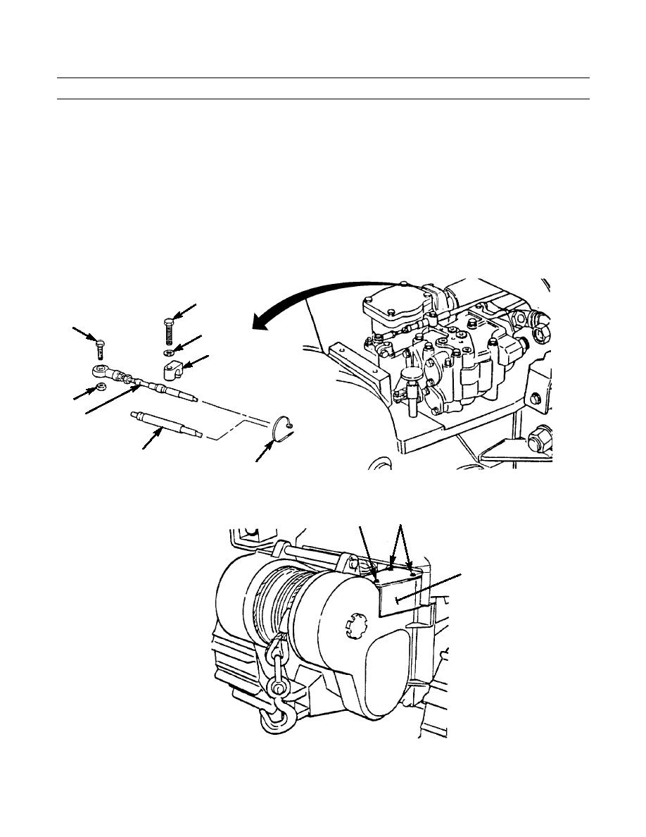
Remove capscrew (42), washer (43) and clamp (44) from control cable (20).
18.
Remove capscrew (45) and self-locking nut (46) from control cable (20). Remove control cable (19) from control valve.
Discard self-locking nut.
19.
Remove control cables (19 and 20) from machine. Remove straps (47) as necessary.
INSTALLATION
1.
Install control cables (19 and 20) to machine. Install straps (47) as necessary.
2.
Install control cable (19) to control valve. Install control cable (20) with capscrew (45) and new self-locking nut (46).
3.
Install capscrew (42), washer (43) and clamp (44) to control cable (20).
42
45
43
44
46
20
19
47
387-423
4.
Install cover (41) on winch control valve with two capscrews (38), capscrews (39) and four new lockwashers (40).
39,40
38,40
41
387-387
0183 00-4
|
|
Privacy Statement - Press Release - Copyright Information. - Contact Us |